
Transmitting-reflecting projection screen, and projection system comprising the same

a projection screen and projection system technology, applied in the field of projection systems, can solve the problems of difficult to sharply display images on holographic screens under bright environmental light, difficult to achieve the effect of sharp image display, improved image contrast, and efficient scattering

Inactive Publication Date: 2010-05-18
DAI NIPPON PRINTING CO LTD
View PDF21 Cites 7 Cited by
  • Summary
  • Abstract
  • Description
  • Claims
  • Application Information

AI Technical Summary

Benefits of technology

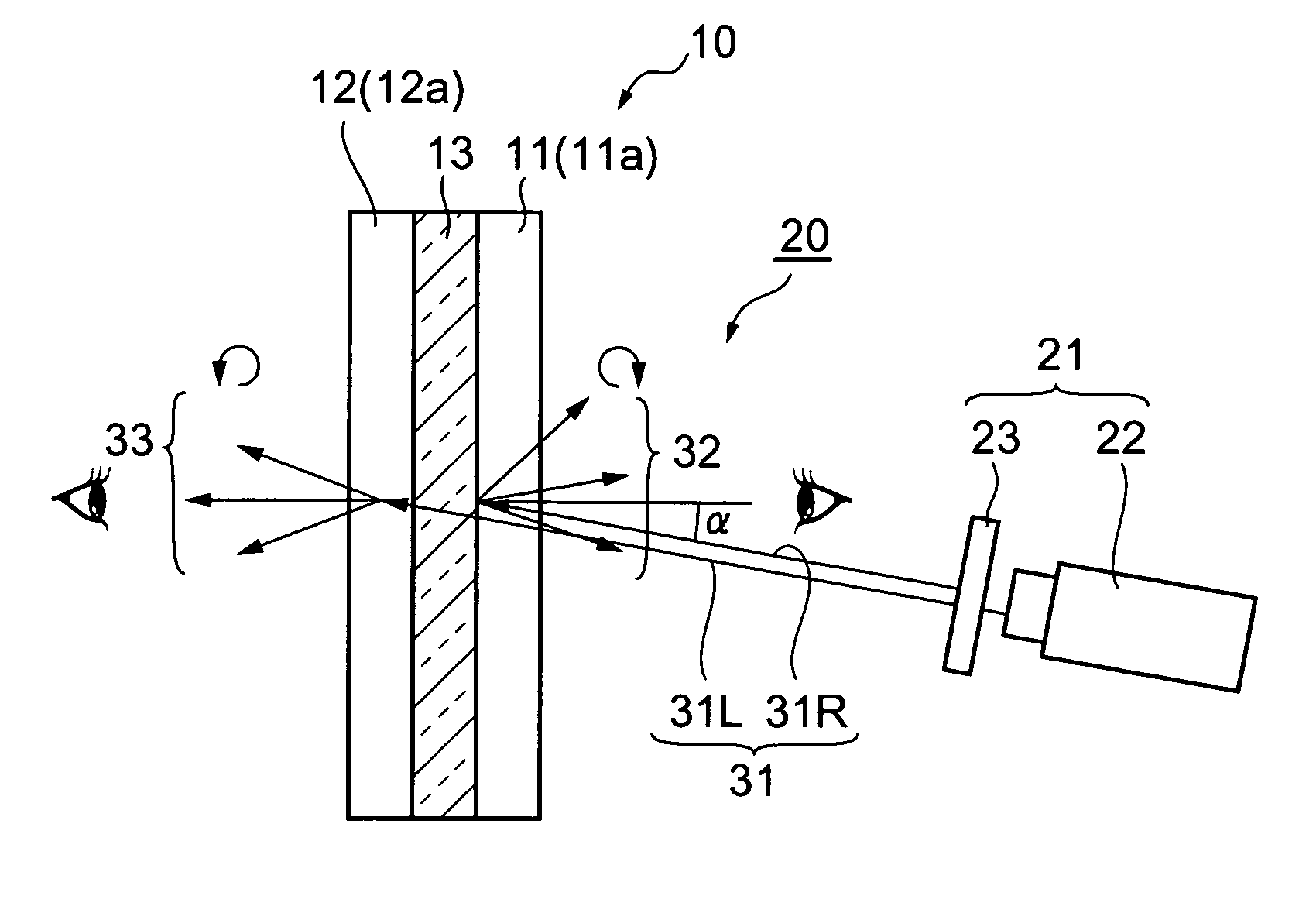
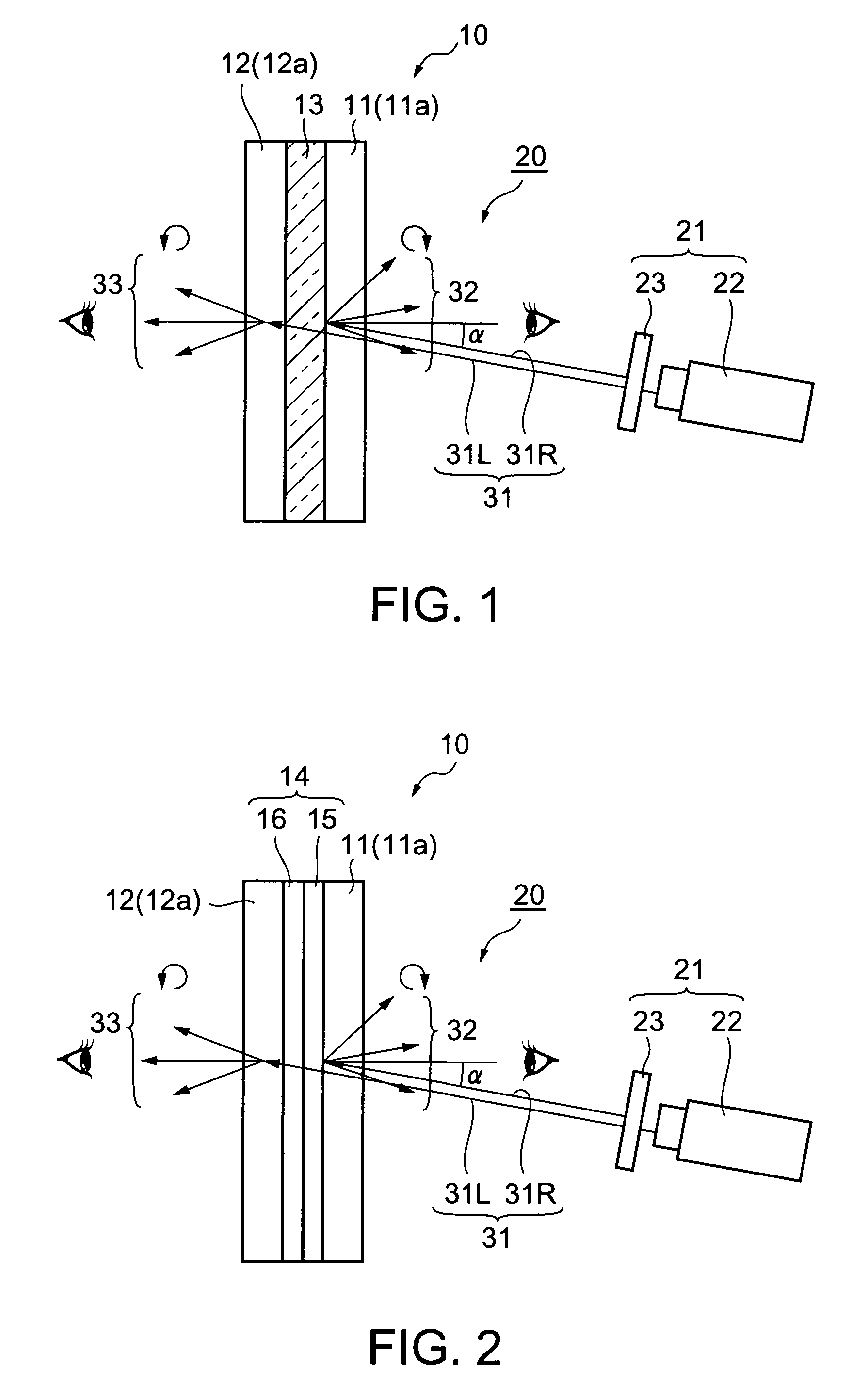
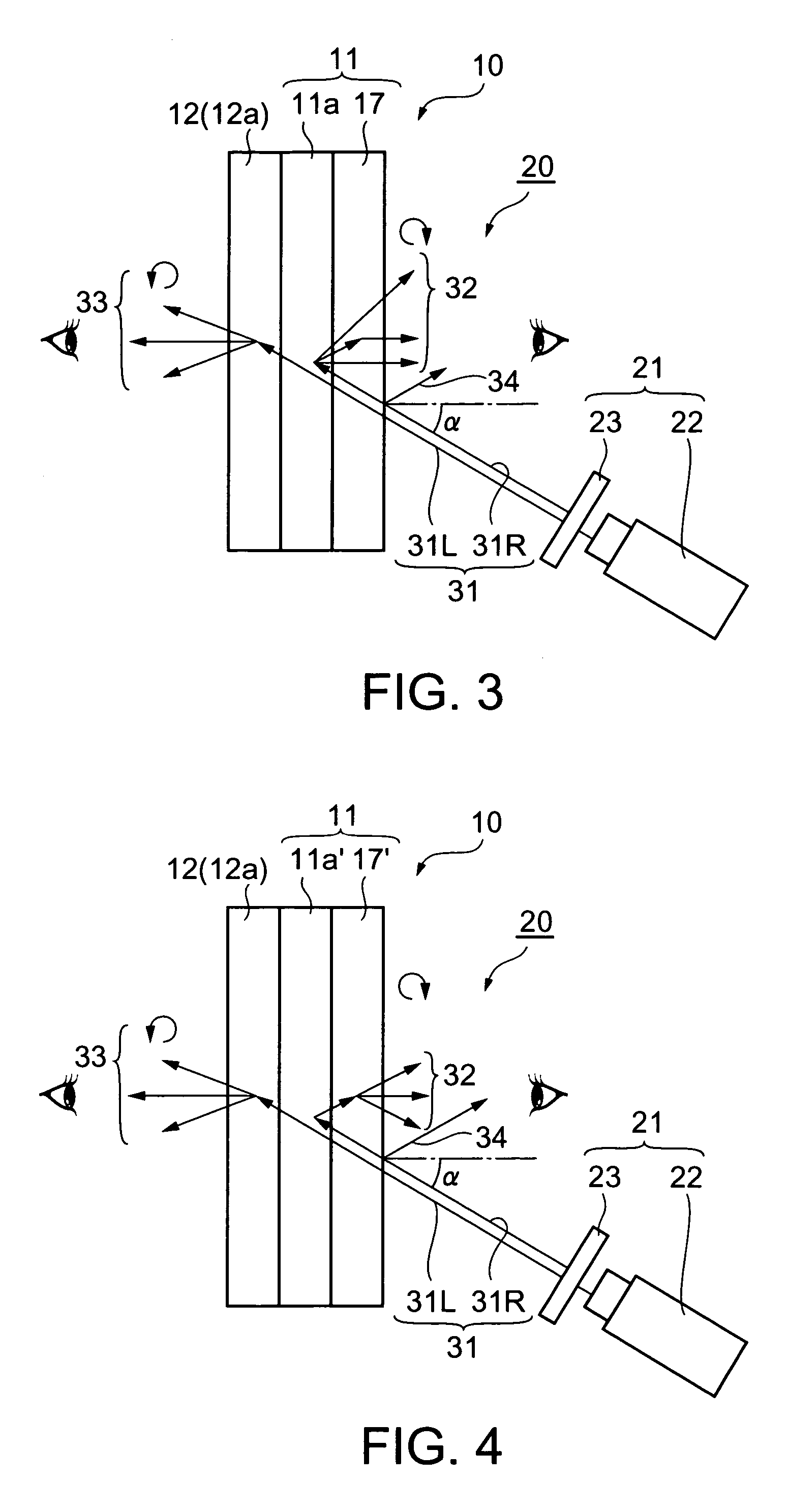
The present invention provides a see-through transmitting-reflecting projection screen that can display images on both sides with clarity and sharpness even in bright environmental light. The screen comprises a reflection-type screen that reflects one specific polarized component of the projected imaging light and a transmission-type screen that transmits a different polarized component. The screen can be used in a projection system with an image projection unit that alternately projects the imaging light for reflection and transmission. The invention also provides a method for making the projection screen. The technical effects of the invention include improved image quality and compatibility with different imaging light polarization characteristics.

Problems solved by technology

However, although the screen described in this patent document can thus display images on its both sides, the viewable images are merely identical ones, and it is theoretically impossible to display on the screen two different images, one on each side of the screen.
The simultaneous projection of two imaging light beams is thus disadvantageous in that the practical installing operation is considerably complicated.
Besides, there exists the following problem with holographic screens themselves: since holograms have wavelength selectivity but no polarized-light selectivity, they cannot separate imaging light from environmental light, which makes it difficult to sharply display images on holographic screens under bright environmental light.

Method used


Image

  • Transmitting-reflecting projection screen, and projection system comprising the same
  • Transmitting-reflecting projection screen, and projection system comprising the same
  • Transmitting-reflecting projection screen, and projection system comprising the same

Examples


examples

[0109]Specific examples of the aforementioned embodiments will now be given below.

[0110]A first cholesteric liquid crystal solution having a selective reflection wave range with a center wavelength of 510 nm was prepared by dissolving, in cyclohexanone, a monomer-containing liquid crystal that had been obtained by adding a chiral agent (5.3% by weight) to an ultraviolet-curing nematic liquid crystal (94.7% by weight), a main component. To the first cholesteric liquid crystal solution was added 5% by weight of a photopolymerization initiator available from Ciba Speciality Chemicals K.K., Japan.

[0111]By way of a bar coating method, the above-prepared first cholesteric liquid crystal solution was applied to a substrate, a 200 mm×200 mm PET film with an adhesion-promoting layer (Lumirror / AC-X manufactured by Panack Co., Ltd., Japan).

[0112]This substrate was then heated in an oven at 80° C. for 90 seconds for alignment (drying). Thus, there was obtained a cholesteric liquid crystal layer...


PUM


Abstract

The present invention provides a see-through transmitting-reflecting projection screen excellent in transparency, capable of sharply displaying, on its both sides, identical or different images even under bright environmental light.A transmitting-reflecting projection screen 10 comprises a reflection-type screen 11 and a transmission-type screen 12. The reflection-type screen 11 reflects a specific polarized component of imaging light projected. The reflection-type screen 11 does not reflect a polarized component, different from the specific polarized component, of the imaging light, and this polarized component passes through the reflection-type screen 11 and the transmission-type screen 12.

Description

FIELD OF THE INVENTION[0001]The present invention relates to a projection system in which imaging light is projected, from a projector, on a projection screen to display thereon an image, and, more particularly, to a see-through transmitting-reflecting projection screen excellent in transparency, capable of sharply displaying images on its both sides by reflecting and transmitting imaging light projected, and to a projection system comprising such a projection screen.BACKGROUND ART[0002]A conventional projection system is usually as follows: imaging light emitted from a projector is projected on a projection screen, and viewers observe the light reflected from the projection screen as an image. Specific examples of projection screens for use in such conventional projection systems include white-colored paper or cloth materials, and plastic films coated with ink that scatters white light. Besides, higher-quality projection screens that comprise scattering layers containing beads, pea...

Claims


Application Information

Patent Timeline
Patent Type & Authority Patents(United States)
IPC IPC(8): G03B21/56G02B5/30G02B5/32G03B21/00G03B21/60G03B21/604G03B21/62
CPCG03B21/62G03B21/604
Inventor KUMASAWA, TOMOKOUMEYA, MASANORIWATANABE, MASACHIKAYAMAUCHI, TSUYOSHI
Owner DAI NIPPON PRINTING CO LTD
Learn More