Image matching method, program, and image matching system

a matching method and image technology, applied in the field of image matching methods and program, can solve the problems of difficulty in suitably generating correlation values and insufficient matching precision, and achieve the effect of high precision

Inactive Publication Date: 2010-05-18
SONY CORP
View PDF18 Cites 28 Cited by
  • Summary
  • Abstract
  • Description
  • Claims
  • Application Information

AI Technical Summary

Benefits of technology

[0006]An object of the present invention is to provide an image matching method capable of matching images with a high precision and a program and an image matching system for the same.

Problems solved by technology

In the above information processing apparatuses, however, when parallel movement, rotation, enlargement, reduction, or other offset occurs between a registered image and the match image, it is difficult to suitably generate the correlation values, so sufficient matching precision is sometimes not obtained.

Method used


Image

  • Image matching method, program, and image matching system
  • Image matching method, program, and image matching system
  • Image matching method, program, and image matching system

Examples


first embodiment

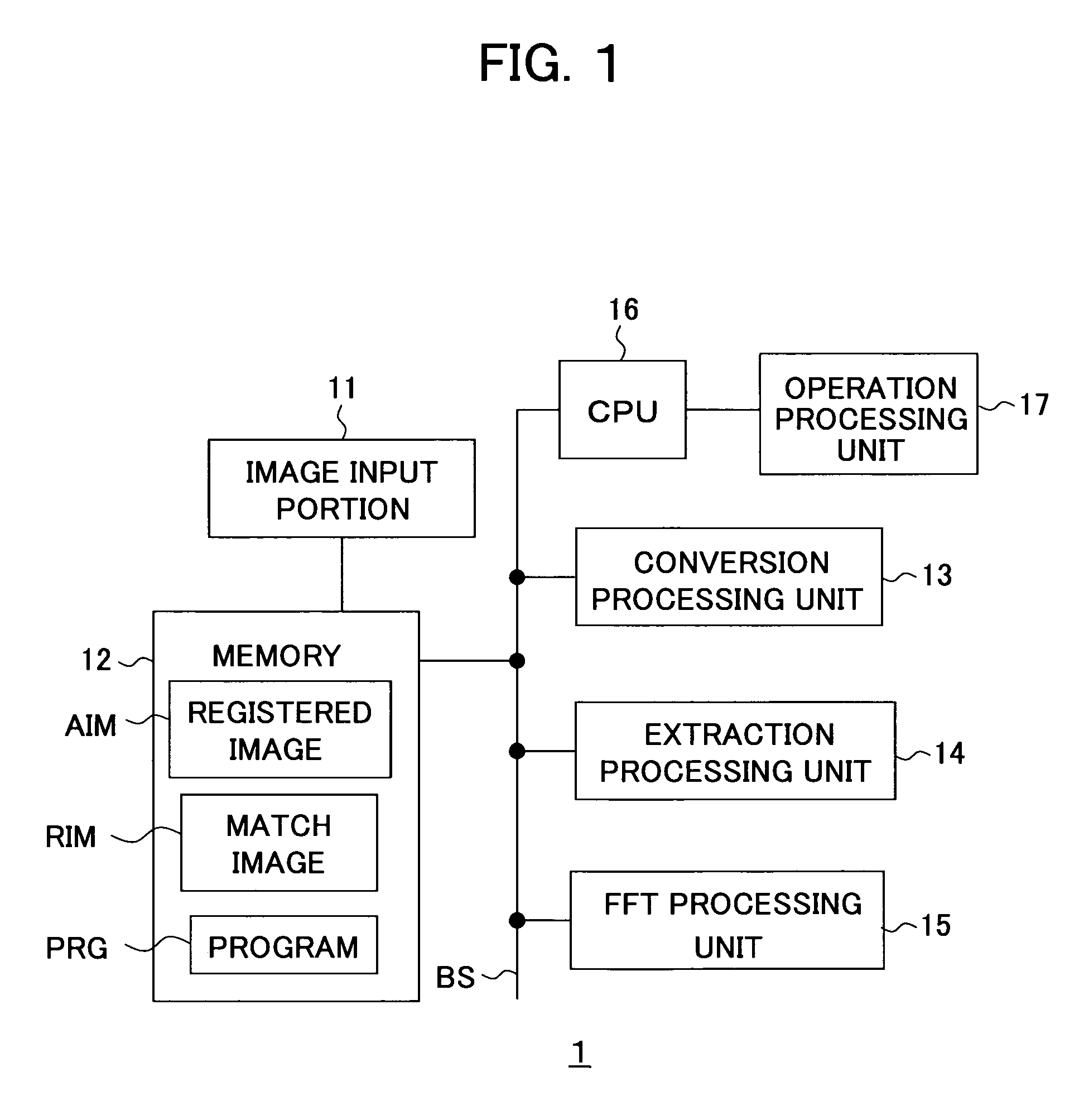
[0031]FIG. 1 is a hardware-like functional block diagram of an image matching system according to the present invention. An image matching system (information processing apparatus) 1 according to the present embodiment, for example, as shown in FIG. 1, has an image input portion 11, a memory 12, a conversion processing unit 13, an extraction processing unit 14, a fast Fourier transform (FFT) processing unit 15, a central processing unit (CPU) 16, and an operation processing unit 17. For example, the image input portion 11 is connected to the memory 12. The memory 12, the conversion processing unit 13, the extraction processing unit 14, the FFT processing unit 15, and the CPU 16 are connected by a bus BS.

[0032]The image input portion 11 is an input portion for receiving input of an image from the outside. For example, the image input portion 11 receives as input a registered image AIM and an image to be compared against the registered image AIM (also referred to as a “match image RIM...

second embodiment

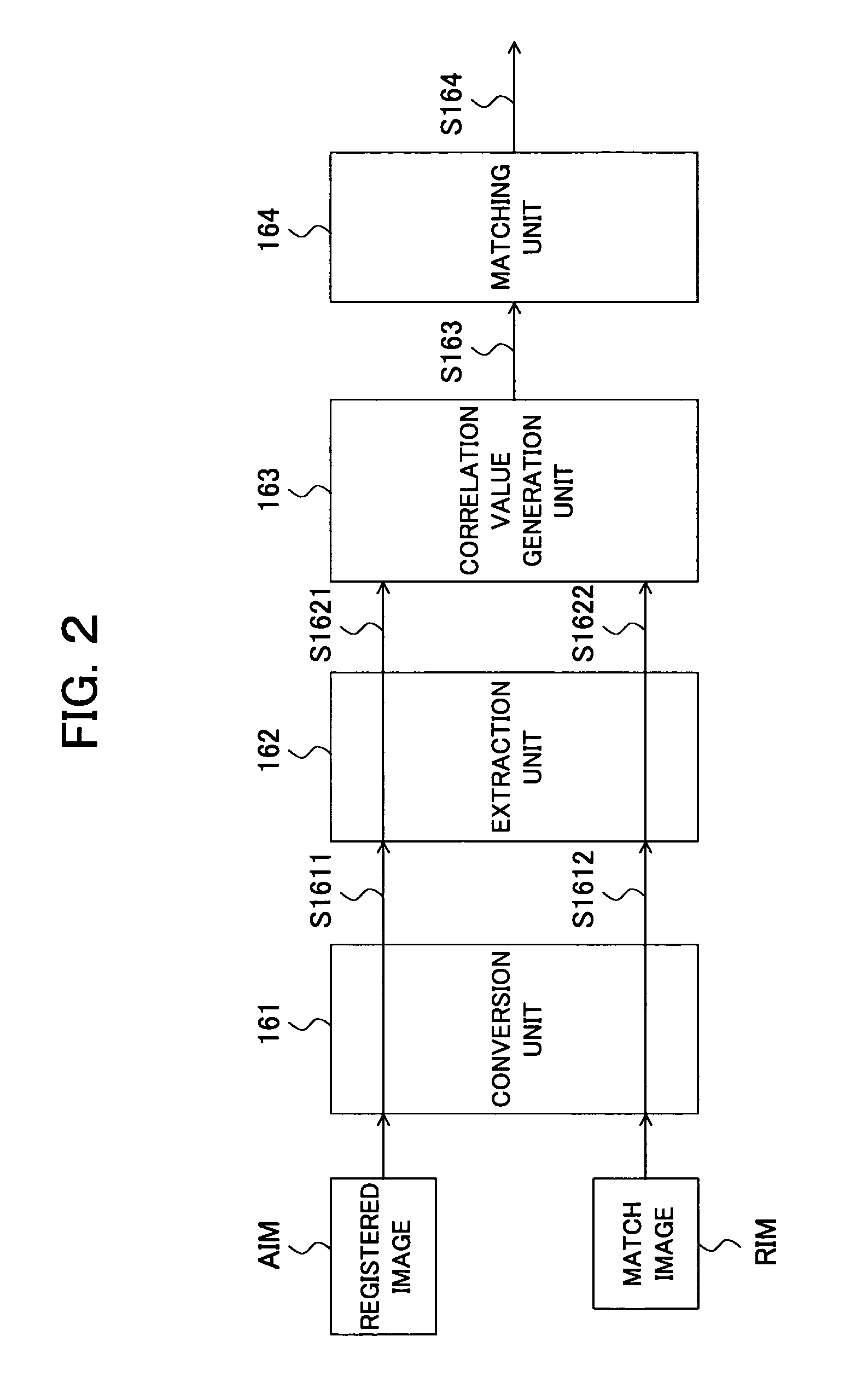
[0080]FIG. 10 is a functional block diagram of the image matching system according to the present invention. An image matching system 1a according to the present embodiment performs Huff conversion processing based on the registered image AIM and the match image RIM, corrects the parallel movement offset of the converted images, generates the similarity as the correlation value between the converted images after the position correction, and performs the matching processing between the registered image AIM and the match image RIM based on the similarity.

[0081]The image processing apparatus 1a has the same components as those of the functional block diagram shown in FIG. 1 in terms of for example hardware, so the explanation will be omitted. The image processing apparatus 1a, in terms of software, for example as shown in FIG. 10, realizes the conversion unit 161, the extraction unit 162, a correlation value generation unit 163a, a position correction unit 170, and a matching unit 164a...

third embodiment

[0104]FIG. 15 is a diagram for explaining the operation of an image matching system according to the present invention. It is determined according to the size of the ρ-θ plane (also referred to as a parameter space) generated by the image conversion processing according to the present embodiment to which extent the straight line on the x-y plane of the image is finely sectioned as a parameter. The larger the size of the parameter space, the finer the straight line can be sectioned, so the higher the resolution by that amount. For example, the conversion unit 161 performs the image conversion processing with a parameter space size of a high resolution (for example, 180×180 pixels) based on an image vb1 including the straight line having a rotation angle offset shown in FIG. 15A and consequently generates an image vb2 shown in FIG. 15B. Further, the conversion unit 161 generates an image vb3 indicating the result of the image conversion processing with a parameter space size of a low ...


PUM


Abstract

An image matching method capable of matching images with a high precision and a program and an image matching system for the same, providing a conversion unit for performing image processing based on a registered image and a match image for converting points in each image to patterns of curves based on a distance from a reference position to the closest point on a straight line passing through each point in the image from the reference position and an angle formed by a straight line passing through the reference position and the closest point and an x-axis as a reference axis including the reference position, converting linear components in the images to patterns of a plurality of overlapped curves, and generating converted images, a correlation value generation unit for performing correlation processing based on the converted images and generating a correlation value, and a matching unit for performing the matching based on a signal indicating the correlation value generated by the correlation value generation unit.

Description

BACKGROUND OF THE INVENTION[0001]1. Field of the Invention[0002]The present invention relates to an image matching method for matching two blood vessel images, fingerprint images, still images, moving images, and other images based on linear components in the images, and a program and an image matching system for the same.[0003]2. Description of the Related Art[0004]Conventionally, as systems for matching image information, various image matching systems are known. For example, an information processing apparatus for comparing for example a registered image against an image for comparison, that is, a “match image”, in a predetermined positional relationship to calculate correlation values and matching a registered image against the match image based on the correlation values or an information processing apparatus generating correlation values by processing in units of pixels are known (refer to for example Japanese Unexamined Patent Publication No. 2000-194862).[0005]In the above in...

Claims


Application Information

Patent Timeline
Patent Type & Authority Patents(United States)
IPC IPC(8): G06K9/36G06T3/20G06T7/00G06T7/40G06V10/48G06T7/60
CPCG06K9/4633G06K9/6232G06K2009/00932G06V40/14G06V10/48G06V10/7715G06F18/213G06T7/60G06T3/20
Inventor IIZUKA, KEN
Owner SONY CORP
Why Eureka
Try Eureka