Reception circuit, radio-controlled timepiece, and reception circuit control method

a technology of reception circuit and radio control, which is applied in the direction of instruments, horology, electric windings, etc., can solve the problems of noise in the output of filtered reception signal from the crystal filter, insufficient cancellation of high frequency noise, and noise in the extraction of signal

Inactive Publication Date: 2010-05-18
SEIKO EPSON CORP
View PDF15 Cites 38 Cited by
  • Summary
  • Abstract
  • Description
  • Claims
  • Application Information

AI Technical Summary

Benefits of technology

[0016]The reception circuit, the radio-controlled timepiece, and the reception circuit control method of the invention can correctly demodulate the received standard time signal.

Problems solved by technology

A problem with the reception circuit taught in JP-A-2003-60520 is that the filtered reception signal output from the crystal filter contains noise resulting from high frequency signal components, for example.
However, if a crystal filter operating at the frequency of the received long-wave standard time signal and a parallel capacitance adjusted to the crystal filter are not provided in parallel, high frequency noise cannot be sufficiently cancelled and the extracted signal will contain noise.
A problem with the reception circuit taught in JP-A-2006-60849 is that the received long-wave standard time signal cannot be correctly demodulated if any deviation in the reference voltage input to the comparator is introduced when manufacturing the reception circuit.
If the reference voltage is set to the median voltage between the peak voltage and the bottom voltage, noise will cause the reception signal to go above or below the reference voltage less frequently and the error rate of the binary signal will therefore drop.
However, if the reference voltage is offset from the median between the top and bottom voltages of the reception signal, the effects of noise may cause a binary signal that is different from the signal that is actually carried by the standard time signal to be output.
When this happens the standard time signal cannot be correctly demodulated.
This problem is exacerbated when the reception circuit can receive different long-wave standard time signals.
As a result, if the reference voltage of the reception circuit is set according to the standard time signal used in Japan and the reception circuit is used to receive the German standard time signal, the voltage at the signal bottom cannot be correctly detected and the standard time signal cannot be correctly demodulated.

Method used


Image

  • Reception circuit, radio-controlled timepiece, and reception circuit control method
  • Reception circuit, radio-controlled timepiece, and reception circuit control method
  • Reception circuit, radio-controlled timepiece, and reception circuit control method

Examples


Embodiment Construction

[0057]Preferred embodiments of the present invention are described below with reference to the accompanying figures.

[0058](1) Timepiece Arrangement

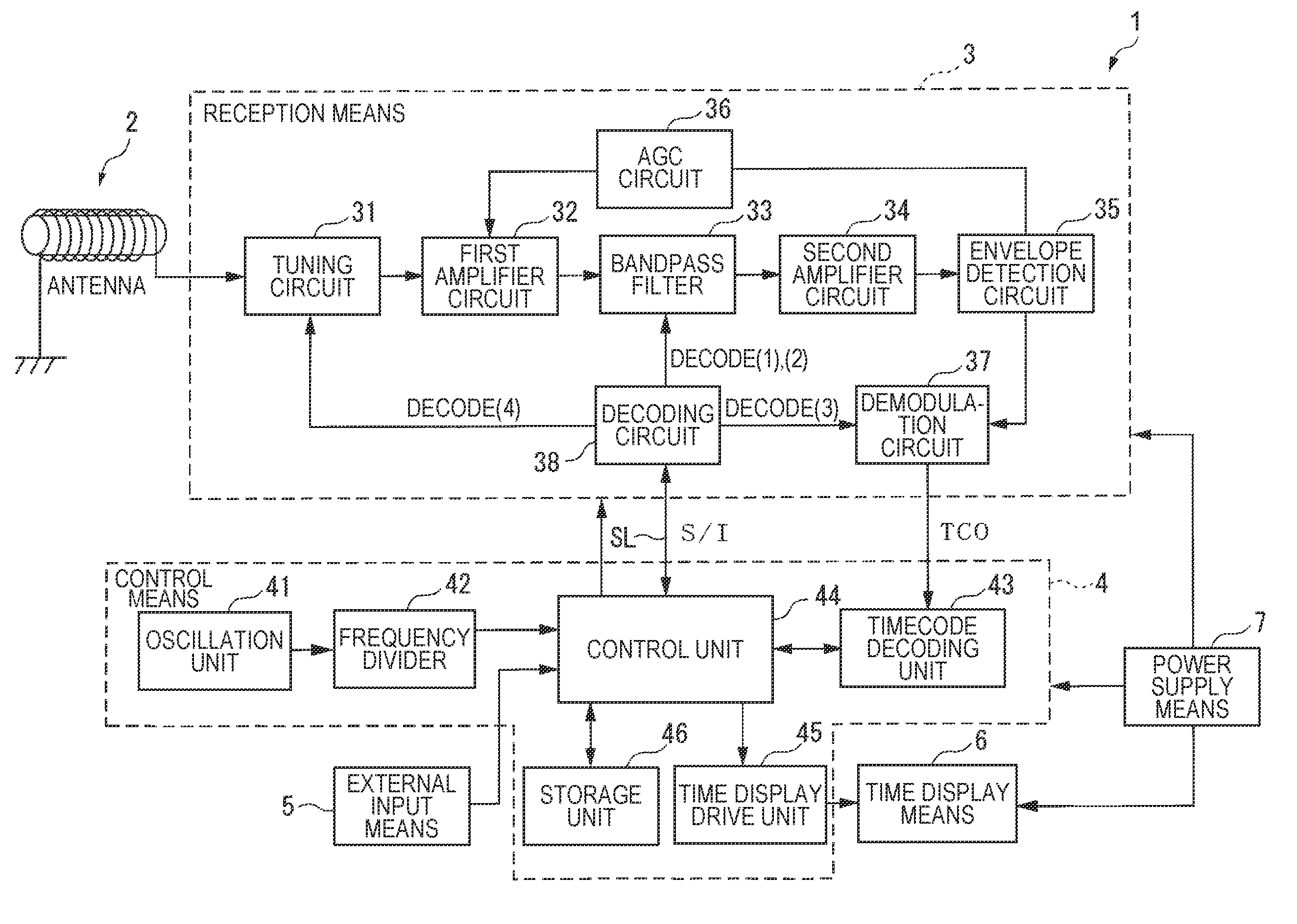
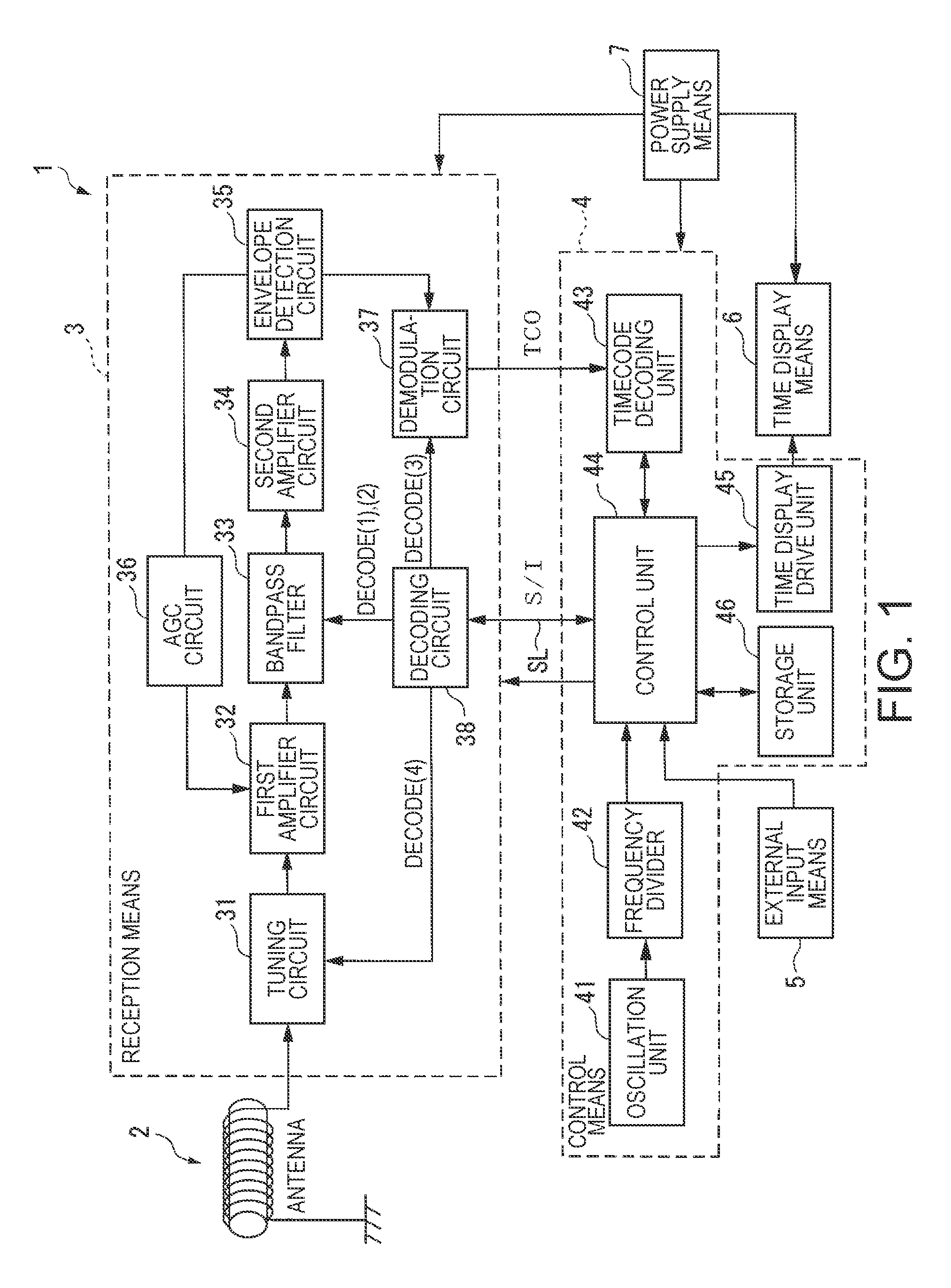
[0059]FIG. 1 is a block diagram showing the arrangement of a timepiece 1 according to a preferred embodiment of the invention.

[0060]The timepiece 1 according to this embodiment of the invention is a radio-controlled timepiece that receives a long-wave standard time signal (also referred to below as simply a standard time signal), demodulates the TCO (timecode output) signal of the standard time signal, and adjusts the internally kept time based on this TCO signal. As shown in FIG. 1 this timepiece 1 has an antenna 2, a reception means 3, a control means 4, an external input means 5, a time display means 6, and a power supply means 7.

[0061]The external input means 5 is used by the user to operate the timepiece 1, and could be the crown or a button, for example.

[0062]The time display means 6 displays the time, and could be an analog display...


PUM


Abstract

A reception circuit can receive a plurality of standard time signals and has a reception means for selectively receiving and demodulating any one of the plural standard time signals, and a control means for outputting a control signal that controls the reception means. The reception means includes a signal amplifier unit for amplifying a reception signal representing the received standard time signal; a signal extraction unit for extracting a signal of a specific frequency from the amplified reception signal; a rectifier unit for rectifying the extracted signal of the specific frequency; and a demodulation unit for demodulating the rectified signal of the specific frequency. The signal extraction unit includes a plurality of crystal filters corresponding to the frequencies of the plural standard time signals; a plurality of parallel capacitances corresponding to the plural crystal filters and parallel connected to the plural crystal filters; a filter switching unit for switching the plural crystal filters based on the control signal; and a parallel capacitance switching unit for switching the plural parallel capacitances based on the control signal. The control means outputs to the filter switching unit and the parallel capacitance switching unit a control signal denoting the switch states enabling the reception means to receive the standard time signal.

Description

CROSS-REFERENCE TO RELATED APPLICATIONS[0001]Japanese Patent application No. 2006-191870 is hereby incorporated by reference in its entirety.BACKGROUND OF THE INVENTION[0002]1. Field of the Invention[0003]The present invention relates to a reception circuit, a radio-controlled timepiece having the reception circuit, and a control method for the reception circuit.[0004]2. Description of the Related Art[0005]Radio-controlled timepieces that automatically correct the internally kept time to display the current time based on timecode information contained in a long-wave standard time signal are known from the literature. This type of radio-controlled timepiece has an internal reception circuit for receiving the long-wave standard time signal and outputting the time code. Japanese Unexamined Patent Appl. Pub. JP-A-2003-60520 (FIG. 2), for example, teaches a reception circuit that amplifies, detects, and demodulates a reception signal for the long-wave standard time signal received by the...

Claims


Application Information

Patent Timeline
Patent Type & Authority Patents(United States)
IPC IPC(8): H04B1/18G04C11/02G04C9/00G04G5/00G04R20/00G04R20/10
CPCG04G5/002G04G21/04G04R20/12G04R20/10H04B1/16
Inventor MIYAHARA, FUMIAKIFUJISAWA, TERUHIKO
Owner SEIKO EPSON CORP
Why Eureka
Try Eureka