Intake air control of an internal combustion engine

a technology of internal combustion engine and air intake, which is applied in the direction of electrical control, process and machine control, etc., can solve the problems of complex process by one or more software programs for implementing constant negative pressure control, and it is difficult for feedback control to correct the opening degree of the throttle valve, so as to achieve the effect of minimizing errors

Inactive Publication Date: 2010-05-18
HONDA MOTOR CO LTD
View PDF12 Cites 9 Cited by
  • Summary
  • Abstract
  • Description
  • Claims
  • Application Information

AI Technical Summary

Benefits of technology

[0008]According to one embodiment of the invention, an effective intake air amount is determined through a filtering process that minimizes an error between the desired intake air amount and an actual intake air amount. The actual intake air amount may be detected by an intake air amount detecting means. The reference throttle opening area is determined by referring to the first table based on the effective intake air amount. Thus, a more appropriate reference throttle opening area is determined based on the effective intake air amount in which an error between the desired intake air amount and the actual intake air amount, which is caused by, for example, a secondary air, has been eliminated.

Problems solved by technology

Thus, a process by one or more software programs for implementing the constant negative pressure control may be complex.
Further, depending on the amount of the secondary air, it may be difficult for the feedback control to correct the opening degree of the throttle valve.

Method used


Image

  • Intake air control of an internal combustion engine
  • Intake air control of an internal combustion engine
  • Intake air control of an internal combustion engine

Examples


first embodiment

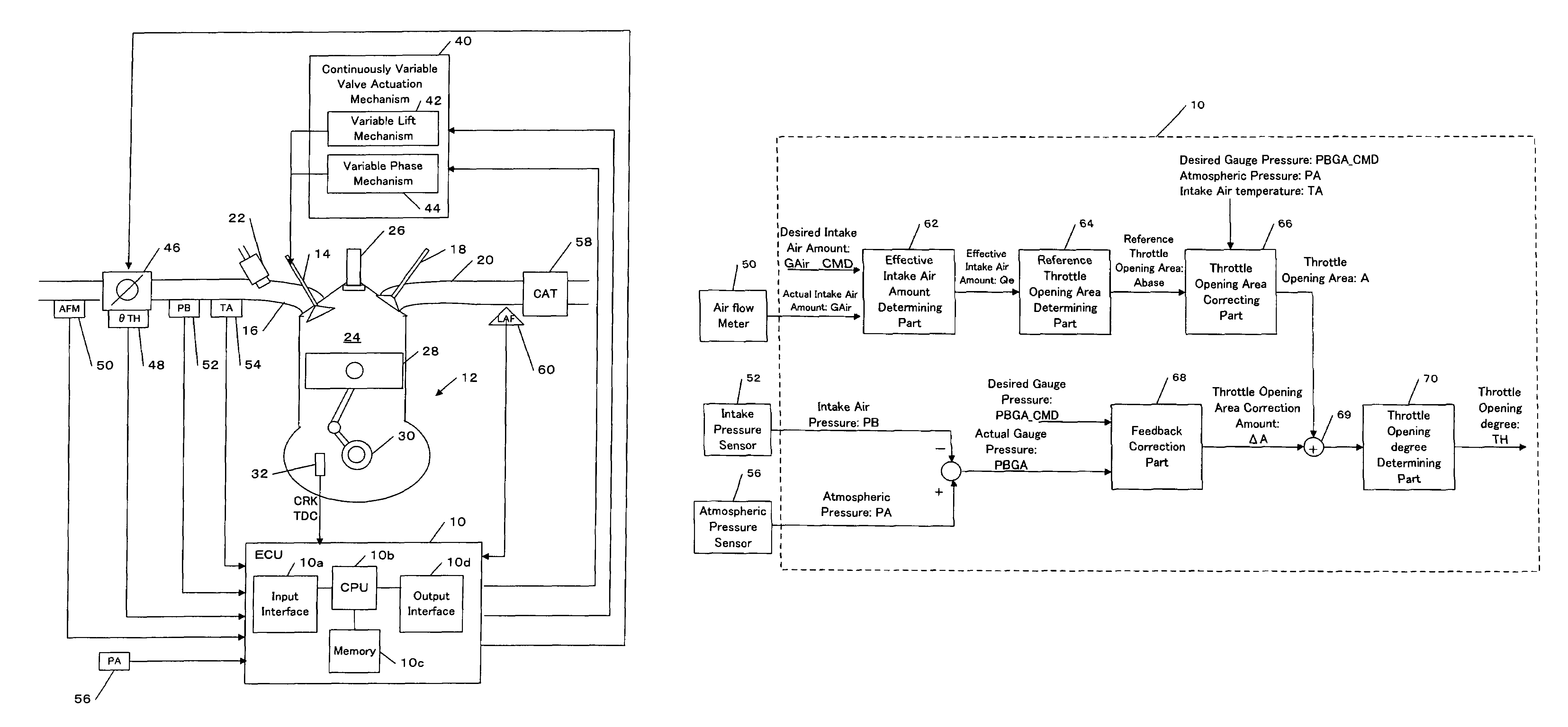
[0050]Referring to FIG. 2, an intake air controlling apparatus of the engine in accordance with the present invention will be described.

[0051]As described above, the intake air controlling apparatus controls the amount of the intake air by adjusting the lift amount of the intake valve 14 via the variable valve actuation mechanism 40. The intake air controlling apparatus also performs the constant negative pressure control for keeping the gauge pressure in the intake manifold 16 at a desired gauge pressure independently of an increase / decrease of the intake air amount. In one embodiment, each function of the intake air controlling apparatus is implemented in the ECU 10. The CPU 10b of the ECU 10 performs one or more programs stored in the memory 10c of the ECU 10 to implement the functions.

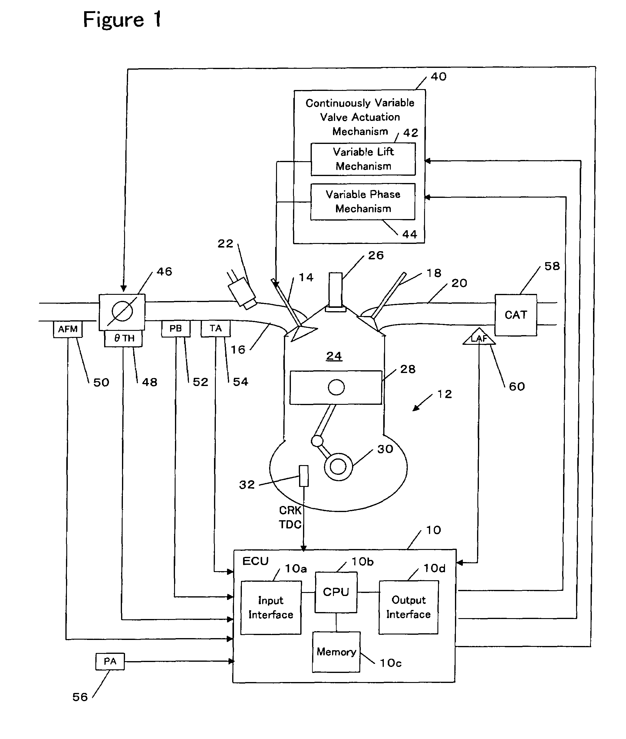
[0052]FIG. 2 shows a detail of functions for the constant negative pressure control in the intake air controlling apparatus. In brief, the constant negative pressure control is formed by two sectio...

second embodiment

[0131]In the second embodiment, as shown in FIG. 9, the adder 69 adds the correction amount ΔA calculated by the feedback correction part 68 to the corrected throttle opening area A2 calculated by the correction part 105.

[0132]The second embodiment further differs from the first embodiment in that a switching part 111 is provided. The switching part 111 calculates a difference ΔPBGA between the actual gauge pressure PBGA and the desired gauge pressure PBGA_CMD. If an absolute value of the difference ΔPBGA is equal to or smaller than a predetermined threshold value, the switching part 111 provides the throttle opening area A2 to the throttle opening degree determining part 70. The throttle opening degree determining part 70 refers to a table as shown in FIG. 7 to determine a throttle opening degree TH corresponding to the throttle opening area A2.

[0133]If the absolute value of the difference ΔPBGA is greater than the predetermined threshold value, the switching part 70 provides a pre...


PUM


Abstract

The present invention provides an intake air control capable of implementing a highly accurate constant negative pressure control with a smaller number of process steps under various environments. The intake air control is applicable to an engine having a variable valve actuation mechanism for adjusting at least a lift amount of an intake valve to control an intake air amount and a throttle valve for keeping a gauge pressure in an intake manifold at a desired gauge pressure. A reference throttle opening area is determined by referring to a first table based on a desired intake air amount. The first table defines a relation between an intake air amount and a throttle opening area under a reference gauge pressure, a reference atmospheric pressure and a reference intake air temperature. A throttle opening area for achieving the desired gauge pressure is determined by correcting the reference throttle opening area with a correction parameter derived based on the Bernoulli's law by using the desired gauge pressure, a current atmospheric pressure and a current intake air temperature.

Description

BACKGROUND OF THE INVENTION[0001]The present invention relates to an intake air control of an internal combustion engine (which will be hereinafter referred to as an “engine”).[0002]Conventionally, a constant negative pressure control for keeping a negative pressure (gauge pressure) in the intake manifold of an engine constant at a desired value by adjusting an opening degree of a throttle valve has been proposed. For example, such a control is disclosed in Japanese Patent Application Publication No. 2000-161120.[0003]According to a conventional scheme for the constant negative pressure control, a table used for determining an opening degree of the throttle valve that implements a desired value of the negative pressure is prepared. When a plurality of desired values of the negative pressure are pre-established, such a table is required for each of the plurality of desired values. One of the tables that corresponds to a current desired value is selected and then an environmental corr...

Claims


Application Information

Patent Timeline
Patent Type & Authority Patents(United States)
IPC IPC(8): G06F19/00F01L1/34F02D11/10F02D9/02F02D45/00
CPCF01L1/34F01L13/0021F01L13/0063F02D11/107F02D13/0226F02D41/0002F02D41/22F01L1/3442Y02T10/18F02D41/08F02D41/1454F02D41/187F02D2041/001F02D2041/1418F02D2041/1432F02D2041/225F02D2200/0402F02D2200/0406F02D2200/703F02D2250/41Y02T10/42Y02T10/12Y02T10/40
Inventor TAKAMIYA, HIDEHARUKOMORIYA, ISAO
Owner HONDA MOTOR CO LTD
Why Eureka
Try Eureka