Fan variable area nozzle for a gas turbine engine fan nacelle with cam drive ring actuation system

a technology of variable area nozzle and fan nacelle, which is applied in the direction of vessel construction, marine propulsion, aircraft navigation control, etc., can solve the problem of increasing the overall engine weigh

Active Publication Date: 2010-05-25
RTX CORP
View PDF37 Cites 100 Cited by
  • Summary
  • Abstract
  • Description
  • Claims
  • Application Information

AI Technical Summary

Benefits of technology

[0010]The present invention therefore provides an effective, lightweight fan variable area nozzle and thrust vectoring system for a gas turbine engine.

Problems solved by technology

Existing fan variable area nozzles typically utilize relatively complex mechanisms that increase overall engine weight to the extent that the increased fuel efficiency therefrom may be negated.

Method used


Image

  • Fan variable area nozzle for a gas turbine engine fan nacelle with cam drive ring actuation system
  • Fan variable area nozzle for a gas turbine engine fan nacelle with cam drive ring actuation system
  • Fan variable area nozzle for a gas turbine engine fan nacelle with cam drive ring actuation system

Examples


Embodiment Construction

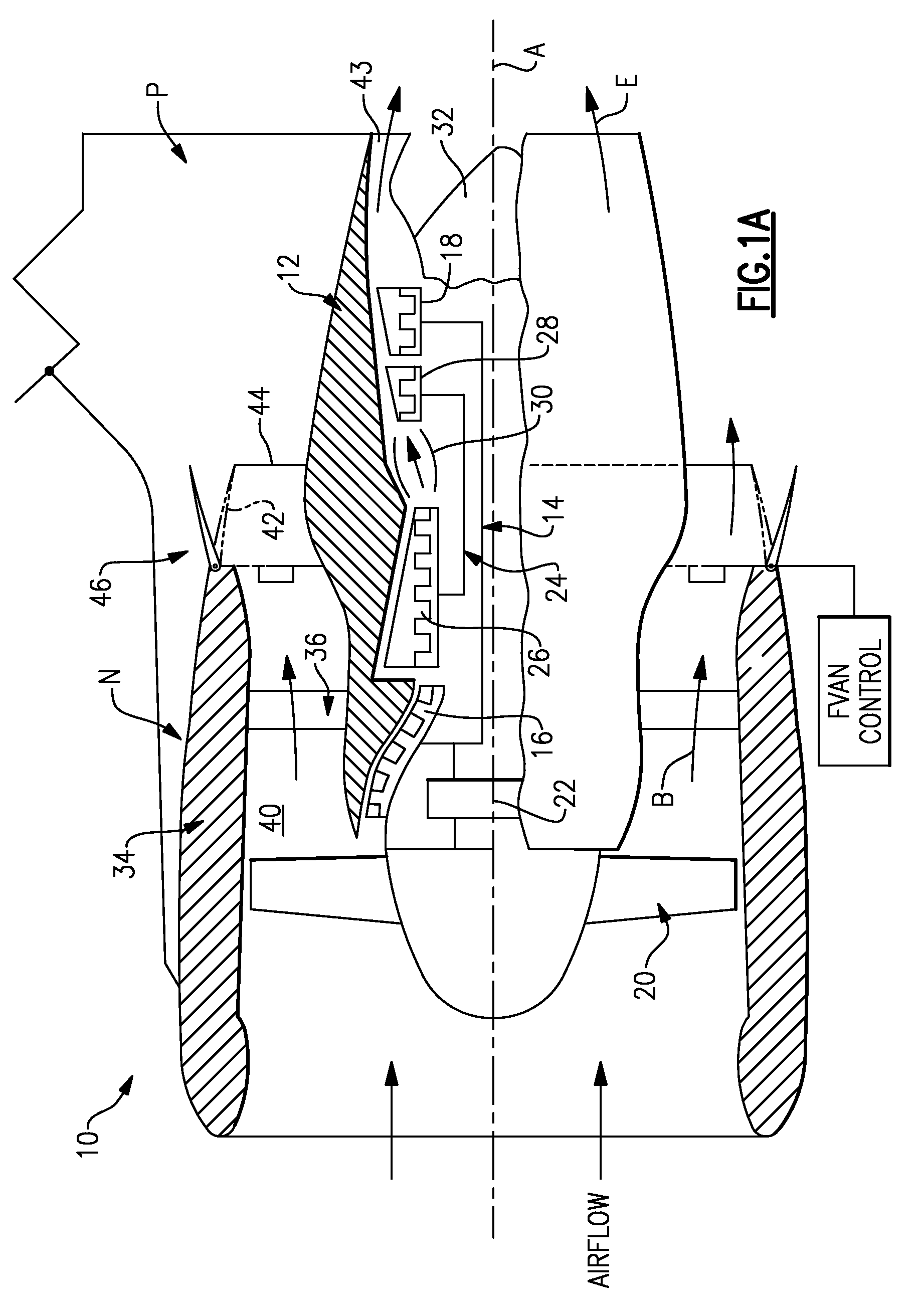
[0027]FIG. 1A illustrates a general partial fragmentary schematic view of a gas turbofan engine 10 suspended from an engine pylon P within an engine nacelle assembly N as is typical of an aircraft designed for subsonic operation.

[0028]The turbofan engine 10 includes a core engine within a core nacelle 12 that houses a low spool 14 and high spool 24. The low spool 14 includes a low pressure compressor 16 and low pressure turbine 18. In the illustrated engine architecture, which is referred to as a geared turbofan, the low spool 14 drives a fan 20 through a gear train 22. The high spool 24 includes a high pressure compressor 26 and high pressure turbine 28. A combustor 30 resides between the high pressure compressor 26 and high pressure turbine 28. The low and high spools 14, 24 rotate independently about an engine axis of rotation A.

[0029]The engine 10 is preferably a high-bypass geared turbofan aircraft engine. Preferably, the engine 10 bypass ratio is greater than ten (10), the tur...


PUM


Abstract

A fan variable area nozzle (FVAN) includes a flap assembly which varies a fan nozzle exit area through a cam drive ring. The flap assembly generally includes a multiple of flaps, flap linkages and an actuator system. The actuator system rotationally translates the cam drive ring relative an engine centerline axis which results in a follower of the flap linkage following a cam surface to pivot each flap such that the flap assembly dilates about the circumferential hinge line. Rotation of the cam drive ring adjusts dilation of the entire fan nozzle exit area in a symmetrical manner. Another cam drive ring includes a multiple of movable cams which engages the follower of the flap linkage of each flap such that pivotable movement of a particular number of the multiple of movable cams about a respective cam pivot results in vectoring of the FVAN.

Description

BACKGROUND OF THE INVENTION[0001]The present invention relates to a gas turbine engine, and more particularly to a turbofan engine having an axial and rotationally moveable drive ring to provide symmetrical and asymmetrical control of the fan nozzle exit area and the direction of the engine thrust vector.[0002]Conventional gas turbine engines generally include a fan section and a core engine with the fan section having a larger diameter than that of the core engine. The fan section and the core engine are disposed about a longitudinal axis and are enclosed within an engine nacelle assembly.[0003]Combustion gases are discharged from the core engine through a core exhaust nozzle while an annular fan flow, disposed radially outward of the primary airflow path, is discharged through an annular fan exhaust nozzle defined between an outer fan nacelle and an inner core nacelle. A majority of thrust is produced by the pressurized fan air discharged through the fan exhaust nozzle, the remain...

Claims


Application Information

Patent Timeline
Patent Type & Authority Patents(United States)
IPC IPC(8): F02K1/00
CPCF02K1/002F02K3/06F02K1/1207Y10T74/2101
Inventor BARAN, KENNETH C.
Owner RTX CORP
Why Eureka
Try Eureka