Fitting

a technology of fittings and joints, applied in the field of fittings, can solve the problems of large structural damage, difficult production of line pipes of compression connections, and inability to detect leaks, and achieve the effect of reducing diameter and producing inexpensively

Inactive Publication Date: 2010-05-25
YORKSHIRE FITTINGS
View PDF10 Cites 7 Cited by
  • Summary
  • Abstract
  • Description
  • Claims
  • Application Information

AI Technical Summary

Benefits of technology

[0011]The invention provides a fitting for connecting lengths of pipe or tube by compression which provides guidance for the length of pipe or tube for fitting, which ensures that there is a leak in the fitted but uncompressed state, and which can, in addition, be produced inexpensively.
[0015]In an embodiment of the invention, the internal contour has at least one narrowing in diameter against which at least one length of pipe or tube can be brought into abutment. This ensures a minimum spacing between the two lengths of pipe or tube which are to be introduced into the fitting on both sides, thereby counteracting the possibility of the connection being sealed in the uncompressed state as a result of the lengths of pipe or tube which are to be connected resting against one another in an exact fit. The narrowing of diameter is advantageously produced all round; a narrowing of diameter at a point is also possible.
[0016]In a development of the invention, a notch is made in the outside of the fitting, thereby forming the narrowing of diameter in the internal contour of the fitting. This makes it possible for the narrowing of diameter to be produced inexpensively.
[0018]The invention provides a connecting arrangement for connecting lengths of pipe or tube by compression which provides guidance for the length of pipe or tube for fitting, which ensures that there is a leak in the fitted but as yet uncompressed state, and which, in addition, enables the connection to be made inexpensively.

Problems solved by technology

If a point of connection has accidentally not been compressed, this pressure test normally produces a detectable leak.
However, if there are adverse pairings of the tolerances of the fitting, sealing element and pipe or tube, it may happen that when the pipe or tube is inserted in the connecting socket the sealing element is subjected to pressure between the fitting and pipe or tube in such a way that no visible leak occurs.
Only in subsequent operation does the uncompressed connection become increasingly leaky due to variations in temperature and pressure, which may result in considerable structural damage, particularly where the system is buried.
However, the line pipe of this compression connection is complex to produce.
In addition, it causes considerable storage and stockkeeping expenditure.
Furthermore, when the line pipe is slid into or onto the fitting, the sealing element may be changed in its functional position, in particular the leakage point may be reduced in its dimensions during the rolling or rotating of the sealing element, whereby the desired effect is greatly jeopardised.
This produces a leak in the uncompressed state, which is removed after compression.
However, the sealing element of this compression connection is complicated and cost-intensive to manufacture.
What is more, the desired effect may be greatly jeopardised if, when the pipe or tube is inserted in the connecting socket, the sealing element is rolled or rotated in such a way that the projection of the sealing element is no longer situated in the functional position intended for it.
The sealing element of this compression connection is likewise very complex and cost-intensive to produce.
A deterioration of the desired effect as a result of rolling or rotating of the sealing element also cannot be ruled out.
Something that is disadvantageous about this compression connection is that only a very small tolerance range is available when the fitting, sealing element and pipes are being produced, which means that production is very complicated and cost-intensive.
What is more, the pipe comes to rest in the connecting socket with a relatively large amount of play, as a result of which the pipe may easily slip out of the connecting socket in the course of further installation prior to the compression.
This creates a risk of mis-compression.

Method used


Image

  • Fitting
  • Fitting
  • Fitting

Examples


Embodiment Construction

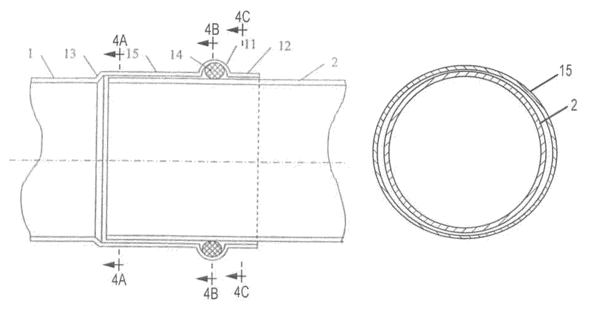
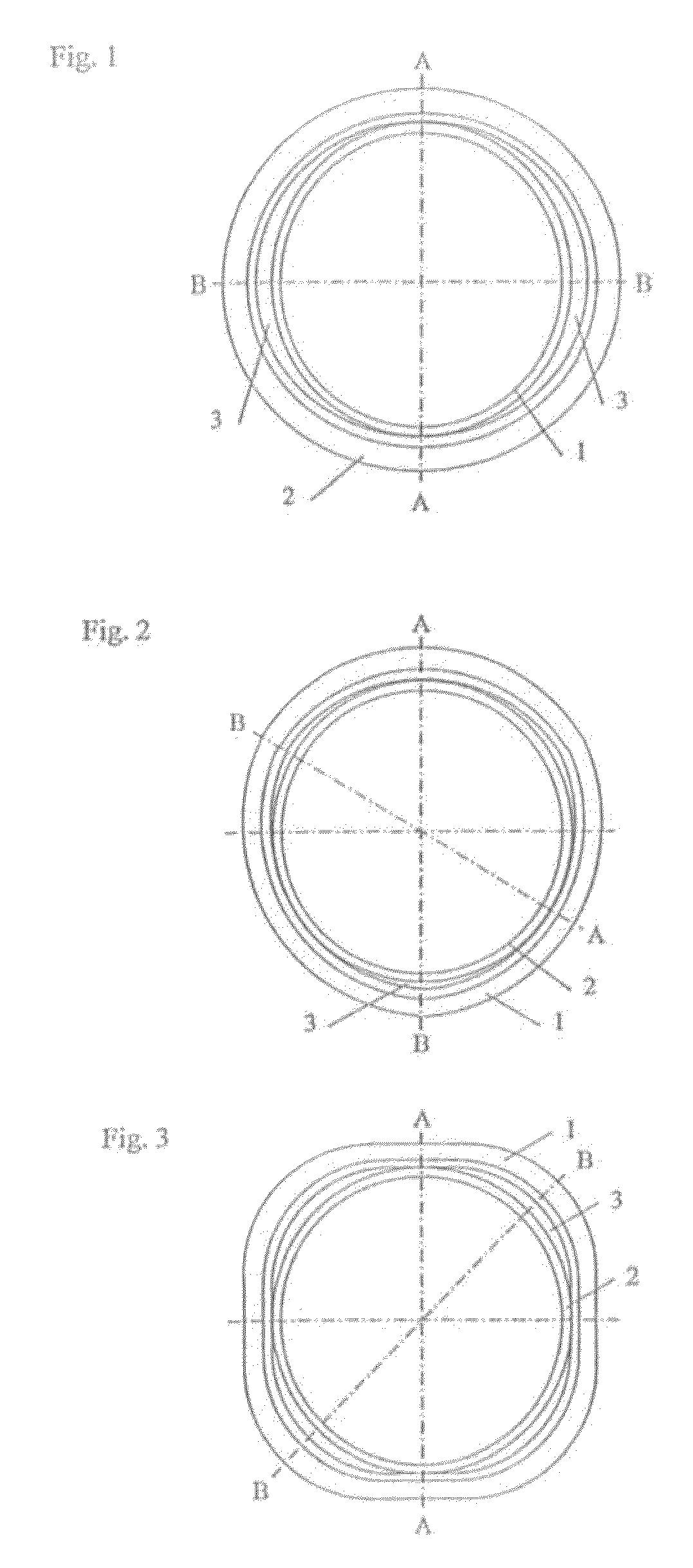
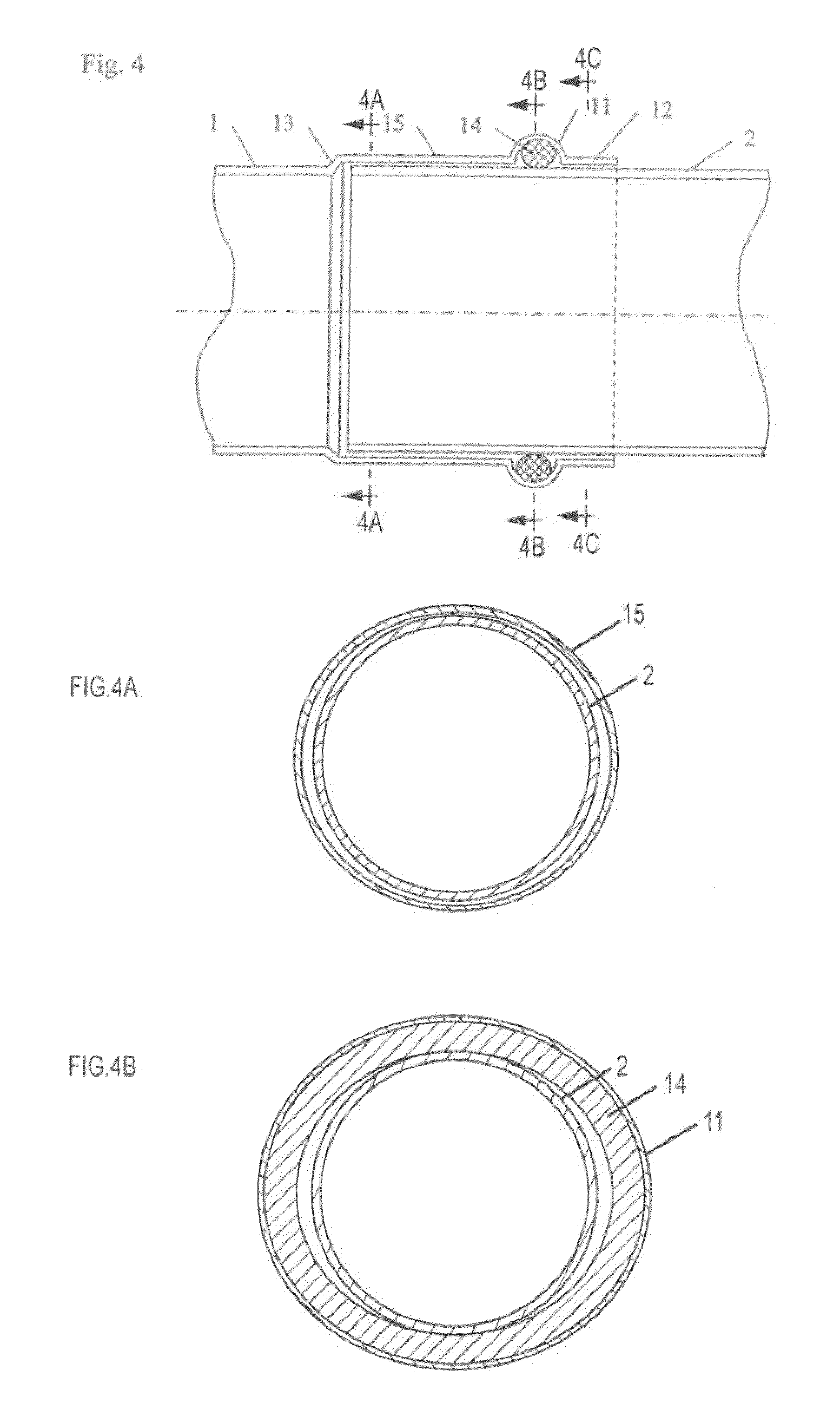
[0031]The connecting arrangement for connecting lengths of pipe or tube by compression which has been selected as an exemplary embodiment in FIGS. 1 to 4 and 4A-4C comprises a fitting 1, into each of the two sides of which a length of pipe or tube 2 is slid. The fitting 1 is substantially in the form of a hollow cylinder. It is made of copper. It is also possible to employ other materials, for example special steel, copper, gunmetal or the like. Provided at each of the two ends of the fitting 1 is a ridge 11 which opens into a collar 12 in the direction of the respective free end. The ridge 11 extends radially around the fitting 1 and has a substantially semi-circular hollow cross-section. Here the ridge 11 is constructed at a constant depth relative to the fitting wall. Provided in the ridge 11 is a sealing element 14 in the form of an O-ring. Running round on the outside, there is provided in the centre of the tilting 1, between the two ridges 11, a notch 13 which produces a reduc...


PUM


Abstract

The invention relates to a fitting for connecting lengths of pipe by compression, having a substantially cylindrical internal contour. The fitting has a ridge which is configured in a radially outward direction and in which a sealing element is provided. The fitting is slidable onto the lengths of pipe, the internal contour having a region of non-circular cross-section. The invention also relates to a connecting arrangement for connecting lengths of pipe by compression, comprising a length of pipe and a fitting plus a sealing element which is arranged in the ridge. One axial gap which extends over the entire connecting region is formed between the length of pipe and the internal contour of the fitting in the uncompressed state. Such an axial gap with an open end would ensure that a leak exists even in the region of the sealing element in an uncompressed state.

Description

CROSS REFERENCE TO RELATED APPLICATIONS[0001]This application is a U.S. national phase of International Patent Application No. PCT / EP2005 / 006842, filed Jun. 24, 2005, entitled “FITTING”, which claims priority to German Patent Application No. 10 2004 031 045.9, filed Jun. 25, 2004, entitled “FITTING”.BACKGROUND OF THE INVENTION[0002]The invention relates to a fitting for connecting lengths of pipe or tube by compression, having a substantially cylindrical internal contour having at least one ridge which is configured in a radially outward direction and in which a sealing element is provided, the fitting being slidable onto the lengths of pipe or tube.[0003]Fittings of the above kind are known per se. Such fittings comprise a connecting socket in which is formed, to receive a sealing element, an elevation radially shaped outwards into a ridge-like form in cross-section. The elevation serves to receive an end of a pipe or tube. To produce a compression connection, the connecting socket...

Claims


Application Information

Patent Timeline
Patent Type & Authority Patents(United States)
IPC IPC(8): F16L21/02F16L13/14
CPCF16L13/148F16L13/142
Inventor HENKE, STEFAN
Owner YORKSHIRE FITTINGS
Why Eureka
Try Eureka