Semiconductor device manufacturing apparatus and method
a manufacturing apparatus and semiconductor technology, applied in the direction of manufacturing tools, grinding drives, lapping machines, etc., can solve the problems of significant affecting productivity, non-uniform polishing of change in the polishing rate, so as to stabilize the uniform amount of polishing on the surface of the wafer
- Summary
- Abstract
- Description
- Claims
- Application Information
AI Technical Summary
Benefits of technology
Problems solved by technology
Method used
Image
Examples
first exemplary embodiment
[0039]FIG. 4 is a plan view seen from a surface of a retainer ring which comes into contact with a polishing pad, used in a first exemplary embodiment of the present invention. Grooves 2a, 2b are formed in a surface of retainer ring 1 which comes into contact with polishing pad 8.
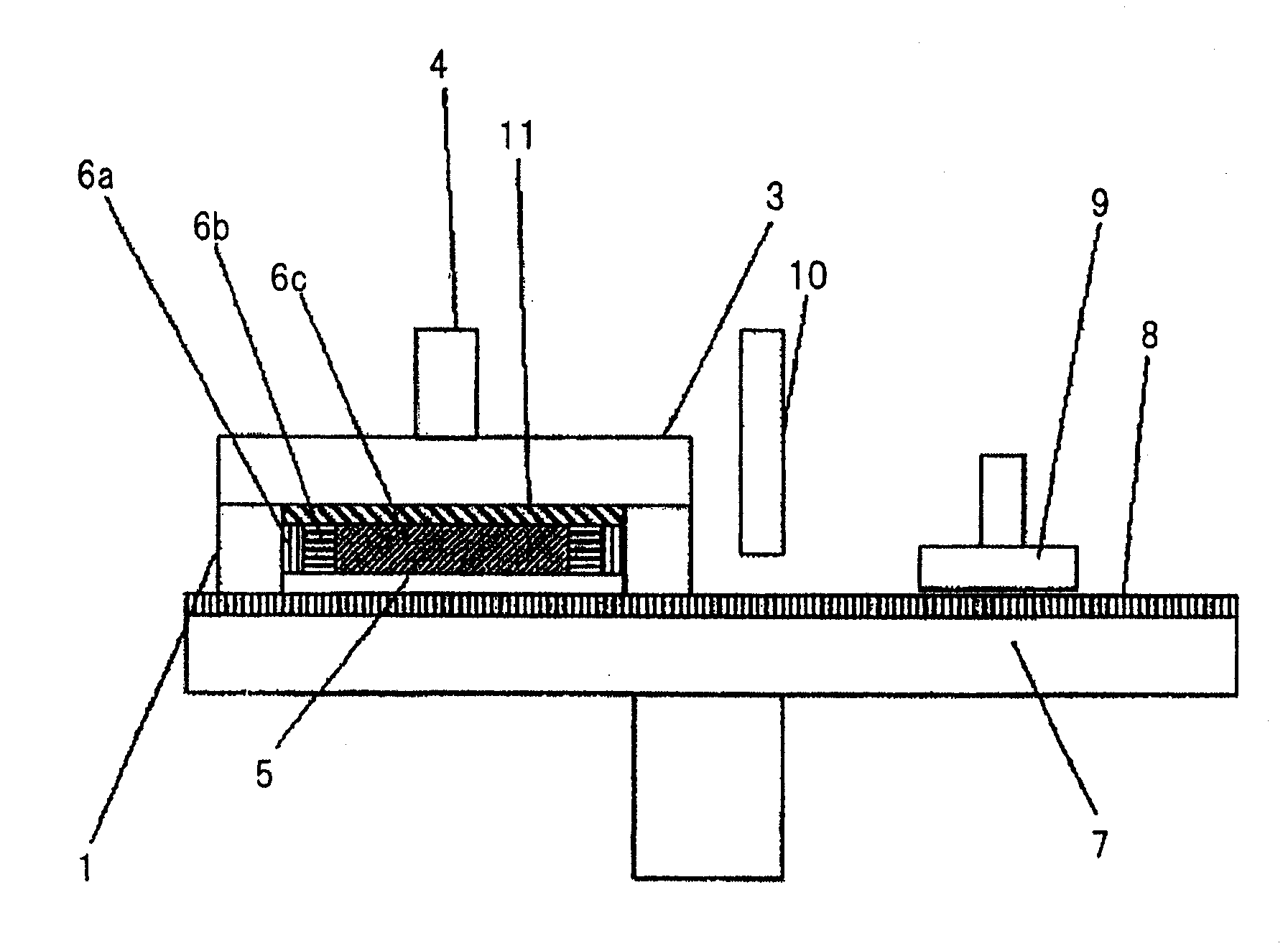
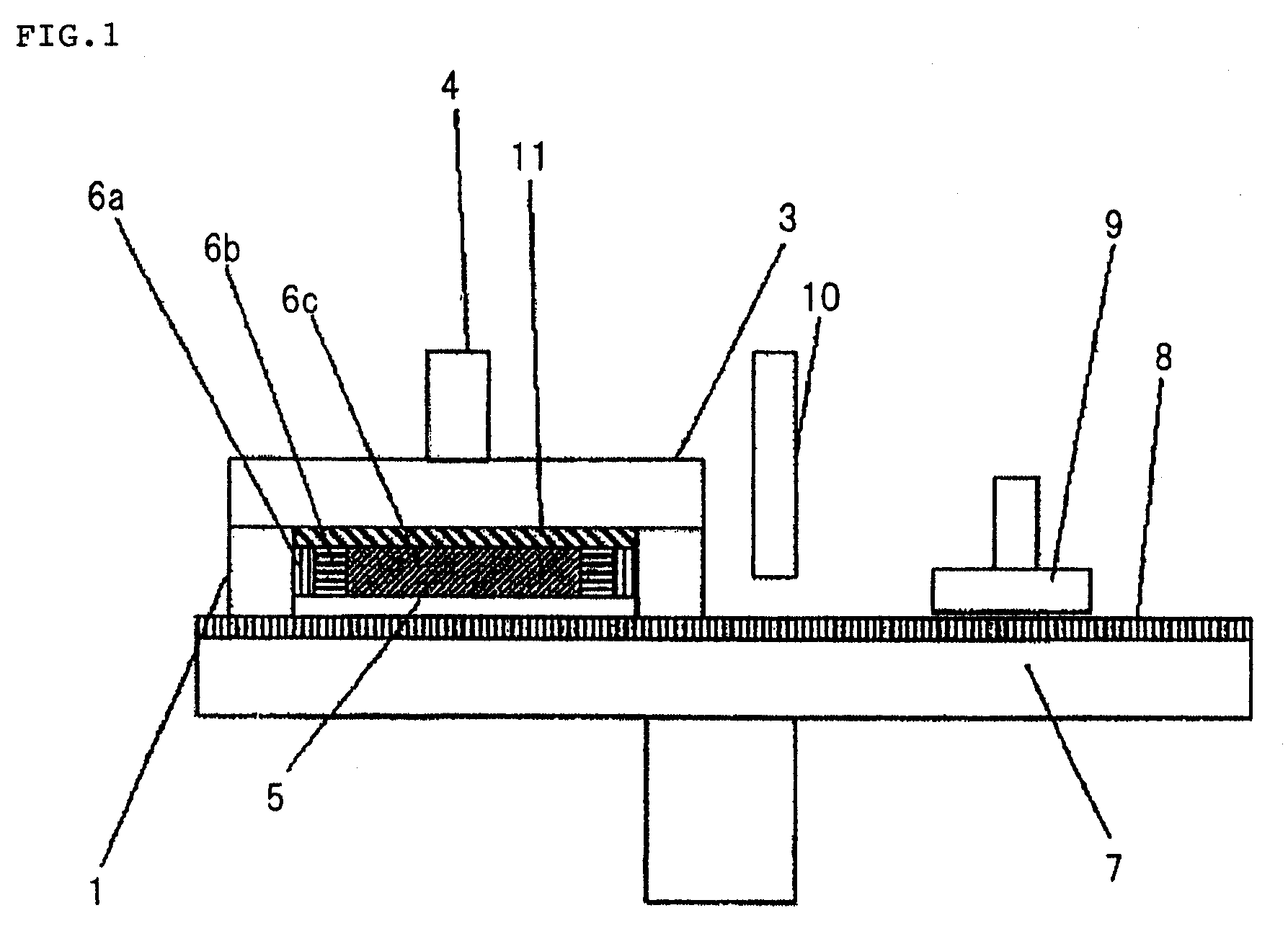
[0040]As previously shown in FIG. 1, such retainer ring 1 is mounted to head 3 which is the main component of a CMP apparatus. Spindle 4 is provided above head 3 for applying a rotating motion to head 3. Membrane 6 is also mounted to head 3, in addition to retainer ring 1, for chucking semiconductor wafer 5 and for applying a pressure on the back surface of semiconductor wafer 5 during polishing. Membrane 6 is divided into several regions, such that different pressures can be applied by membrane 6a to the outermost region of the wafer, to membrane 6b for a region inside of membrane 6a, and to membrane 6c for a wide region of the wafer except for the outer peripheral side. In this way, the surface of semicon...
second exemplary embodiment
[0059]Next, a description will be given of a second exemplary embodiment of the present invention, where the description will be given of only parts different from the CMP apparatus of the first exemplary embodiment.
[0060]FIG. 7 is a cross-sectional view showing the main portion of a retainer ring used in the second exemplary embodiment of the present invention.
[0061]In this exemplary embodiment, the bottom surface of each groove 2b concentrically formed in a surface of retainer ring 1 in contact with polishing pad 8 is machined into a concavely curved shape.
[0062]For example, when the depth of each groove 2b is chosen to be 0.1 mm, 0.2 mm, or 0.3 mm in order inwardly from the outer periphery of retainer ring 1, the bottom surface of each groove 2b is formed with curved area 17 having radius R of approximately 0.05 mm.
[0063]When each groove 2b has a flat bottom surface, the groove is suddenly eliminated due to the advance of wear, and the shock is a concern at that time, but curved ...
third exemplary embodiment
[0065]Next, a description will be given of a third exemplary embodiment of the present invention. Likewise, the description will be given herein only of parts different from the CMP apparatus of the first exemplary embodiment.
[0066]FIG. 8 is a cross-sectional view showing a main portion of a retainer ring used in the third exemplary embodiment of the present invention.
[0067]In this exemplary embodiment, each of the grooves concentrically provided in the surface of retainer ring 1 in contact with polishing pad 8 has the same depth and is tapered toward the bottom of the groove. Specifically, each of the concentric grooves is a tapered groove 2c as shown in FIG. 8, and differs from the first exemplary embodiment in that there are grooves 2b which differ from each other in regard to depth.
[0068]The bottom surface of grooves 2c may be machined into a concavely curved surface as in the second exemplary embodiment.
[0069]Taking such a form of grooves, the correlation of a groove occupation...
PUM
| Property | Measurement | Unit |
|---|---|---|
| depth | aaaaa | aaaaa |
| depths | aaaaa | aaaaa |
| depths | aaaaa | aaaaa |
Abstract
Description
Claims
Application Information
 - R&D
- Intellectual Property
- Life Sciences
- Materials
- Tech Scout
- Unparalleled Data Quality
- Higher Quality Content
- 60% Fewer Hallucinations
Browse by: Latest US Patents, China's latest patents, Technical Efficacy Thesaurus, Application Domain, Technology Topic, Popular Technical Reports.
© 2025 PatSnap. All rights reserved.Legal|Privacy policy|Modern Slavery Act Transparency Statement|Sitemap|About US| Contact US: help@patsnap.com


