Fuse providing circuit isolation and visual interruption indication

a circuit isolation and visual interruption technology, applied in the direction of protective switch operation/release mechanism, protective switch details, etc., can solve the problems of high current, insufficient high voltage fuses, and difficult manufacturing, etc., to achieve the effect of high curren

Active Publication Date: 2010-05-25
THOMAS & BETTS INT INC
View PDF61 Cites 11 Cited by
  • Summary
  • Abstract
  • Description
  • Claims
  • Application Information

AI Technical Summary

Benefits of technology

[0015]It is another object of this invention to provide a fuse which is designed to provide visual indication, and a distinct open section, with relatively low currents that cause the melting of a joint made with a relatively low melting point material (<500° C.).
[0016]It is still another object of this invention to provide a fuse with the previously described characteristics in which the open section(s) are surrounded by granular dielectric filler, the purpose of which is to improve the interrupting capability of the fuse, and to provide a better dielectric withstand after current interruption.
[0020]The biasing feature of the present invention can also be utilized in high current fuses with or without the indicator. Such a fuse would simply include a fuse housing having first and second electrical terminals, a high fault current interrupting element responsive to high currents disposed within the fuse housing and defining an electrical path between the first and second terminals and a biasing element. The high fault current interrupting element has a meltable portion which melts when subject to a high threshold current flowing therethrough to create a gap in the electrical path and the biasing element acts on the high fault current interrupting element for elongating the gap in the electrical path upon melting of the fusible element. Moreover, with such high current fuses, the fuse housing preferably contains a granular dielectric medium therein, and the fusible structure preferably has a sheath surrounding the movable portion of the fusible structure to prevent the granular dielectric medium from interfering with the movement of the movable portion.
[0022]Both the high current element and the solder joint are held in tension such that the melting action causes a physical movement of the element. This physical movement assists in the initiation of an arc, and therefore the current interruption, and provides a high resistance “gap” that is independent of the amount of arcing and therefore recovery voltage. This movement further forces movement of an indicating plunger that can provide either visual indication of the fuse's operation or can complete an external circuit to provide remote indication.

Problems solved by technology

This method does not suffer from the potential deterioration problems inherent in the first method, but is harder to manufacture.
However, there are some applications for which these conventional low voltage fuses are not suitable.
This leads to two potential problems.
This can lead to a relatively high resistance open point, sufficient to prevent current flow in the overloaded cable, but which is not high enough to enable conventional fault finding equipment to be effective at finding the open point, as compared with a fuse which arcs and which would normally have a resistance of many millions of ohms.
This delays the finding and replacing of the operated device.
However, the second problem is that the lack of recovery voltage also prevents conventional indicators from working.

Method used


Image

  • Fuse providing circuit isolation and visual interruption indication
  • Fuse providing circuit isolation and visual interruption indication
  • Fuse providing circuit isolation and visual interruption indication

Examples


Embodiment Construction

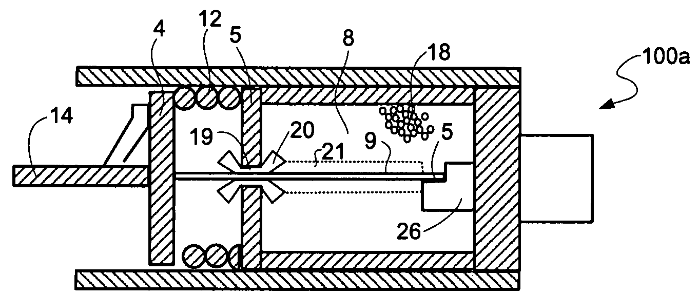
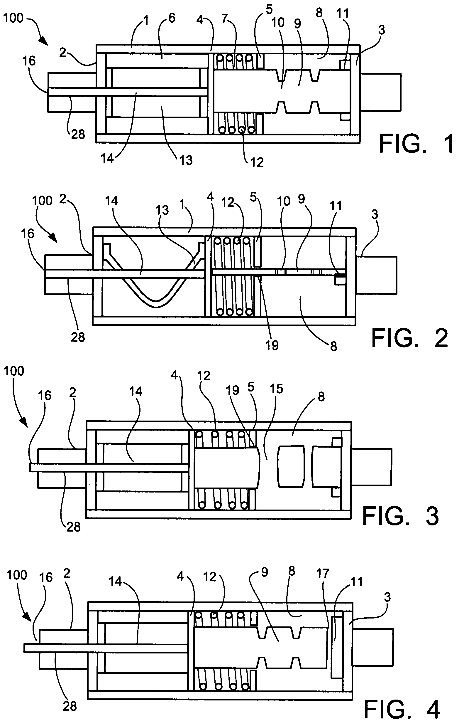
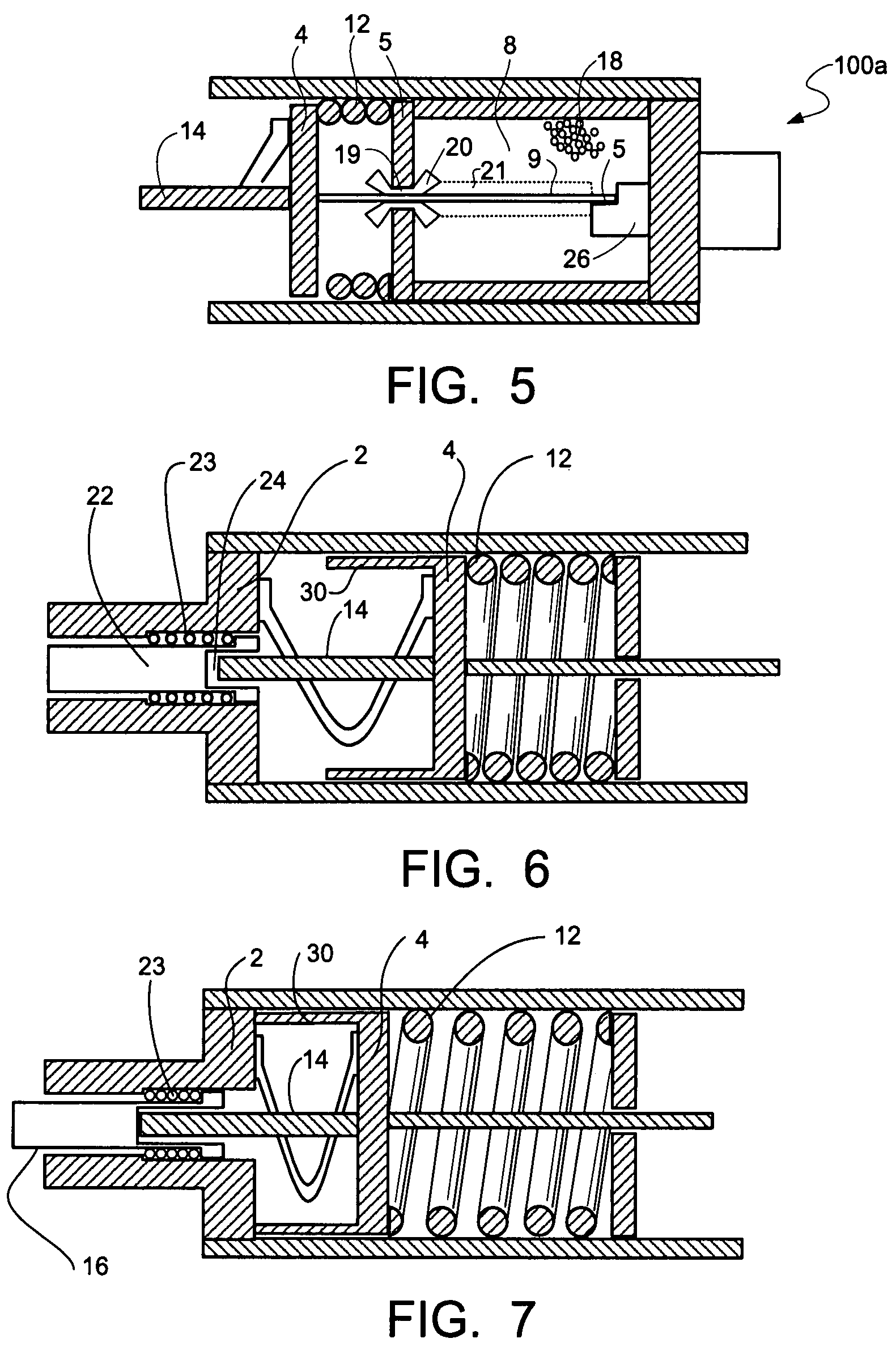
[0033]The significance of the present invention will be best understood by a description of the sequence of events when the device is subjected to both high and low currents.

[0034]Referring first to FIGS. 1 and 2, the fuse 100 of the present invention generally includes an elongate, insulative, non-conducting housing 1 closed at its opposite ends with two conductive terminals 2 and 3, which are electrically connected to a power circuit. A movable partition 4 and a fixed partition 5 divide the interior of the housing 1 into three sections. First section 6 extends between movable partition 4 and the first terminal 2, second section 7 extends between the movable partition 4 and the fixed partition 5 and third section 8 extends between the fixed partition 5 and the second terminal 3.

[0035]The movable partition 4 is made of an electrically conductive material and is generally in the form of a piston-type element, which is able to slide within the interior space of the housing 1. Fixed to...


PUM


Abstract

A fuse including a fuse housing having first and second electrical terminals, a movable partition made from an electrically conductive material movably disposed within the fuse housing, a fusible structure connected between the first electrical terminal and the movable partition, a conductor connected between the movable partition and the second electrical terminal, a biasing element acting on the movable partition to maintain the fusible structure in tension and for moving the movable partition upon melting of the fusible structure and an indicator connected between the movable partition and the second electrical terminal. The conductor, the movable partition and the fusible structure define an electrical path between the first and second electrical terminals and the indicator protrudes out of the second electrical terminal of the fuse housing upon melting of the fusible structure for providing visual indication of an interrupted condition of the fuse when subjected to a threshold current flowing therethrough.

Description

CROSS-REFERENCE TO RELATED APPLICATIONS[0001]This application claims the benefit of U.S. Provisional Application No. 60 / 860,613, filed on Nov. 22, 2006.FIELD OF THE INVENTION[0002]The present invention relates generally to electric current interruption devices and, more particularly, to a low voltage fuse having the ability to provide circuit isolation and indication of operation in circuits presenting little or no voltage across the open fuse.BACKGROUND OF THE INVENTION[0003]A fuse is a protective device for electrical circuits which has a fusible element that melts and opens to interrupt the circuit when subjected to excessive currents. The melting occurs, in large part, due to I2R heating of the fusible element. For many types of fuses, melting at relatively high currents (i.e., currents that produce melting in less than about 1 second) typically occurs at one or more reduced cross-sectional areas of the fusible element, so designed as to control the melting time versus current c...

Claims


Application Information

Patent Timeline
Patent Type & Authority Patents(United States)
IPC IPC(8): H01H85/04H01H37/74H01H37/76H01H71/18H01H85/30
CPCH01H85/36H01H85/303
Inventor LEACH, JOHN G.
Owner THOMAS & BETTS INT INC
Why Eureka
Try Eureka