Pulse domain linear programming circuit

a programming circuit and pulse domain technology, applied in the field of pulse domain linear programming circuits, can solve the problems of limited accuracy of such prior art circuits and limited accuracy of this circui

Active Publication Date: 2010-05-25
HRL LAB
View PDF11 Cites 27 Cited by
  • Summary
  • Abstract
  • Description
  • Claims
  • Application Information

AI Technical Summary

Benefits of technology

[0019]The second type of elements includes a bias element, a leaky integrator, adders, a fixed memory-less non-linearity, a regular integrator, a hysteresis quantizer and a 1-bit self-feedback DAC. The cross-coupling signals between the two types of elements are pulse time-encoded signals. All of the cross-coupling weights are set via 1-bit DACs having variable gains. The cross-coupling weights are used to set a constraint equation of a pulse domain linear programming problem.

Problems solved by technology

Typically, a circuit performing time encoding does not process or solve a linear programming problem.
The accuracy of such prior art circuits is limited by the linearity of the analog amplifier, commonly used in an internal input.
The accuracy of this circuit is limited by the linearity of these variable-gain analog amplifiers.

Method used


Image

  • Pulse domain linear programming circuit
  • Pulse domain linear programming circuit
  • Pulse domain linear programming circuit

Examples


Embodiment Construction

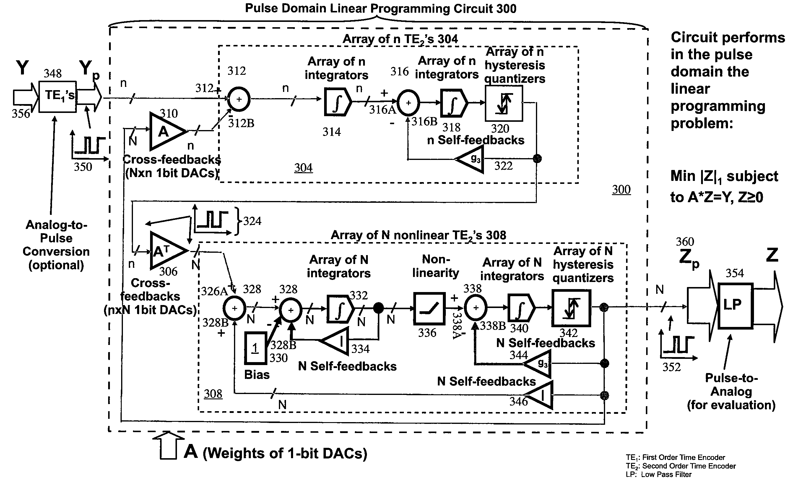
[0030]The present disclosure relates a system and method for making a pulse domain linear programming circuit. Specifically, the pulse domain linear programming circuit can be used for a real-time recovery of signals captured via compressed sensing, in which a linear programming optimization problem is solved in a pulse domain.

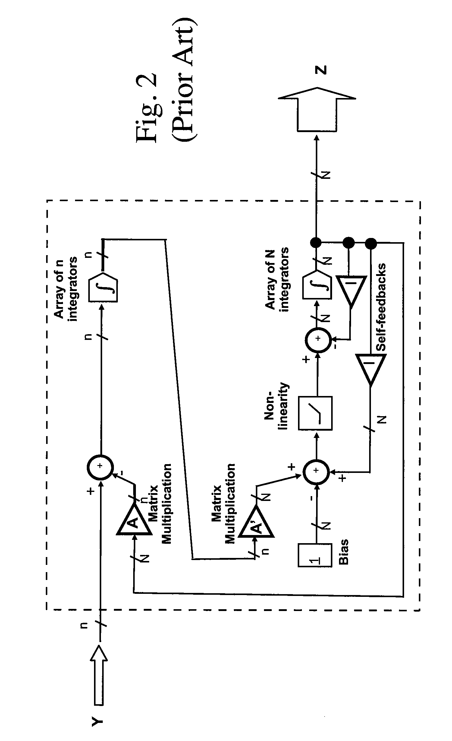
[0031]FIG. 3 shows a block diagram of a pulse domain linear programming circuit 300 of the present disclosure, suitable for solving the linear programming problem of Equation 1 in the pulse domain. The pulse domain linear programming circuit 300 does not need analog variable-gain amplifiers used in the prior art (FIG. 2). The pulse domain linear programming circuit 300, for example, solves in the pulse domain the following linear programming problem:

Min|Z|1 subject to A*Z=Y,Z0.

[0032]That is, minimize |Z|1 subject to the above constraint. |Z|1 is the norm-1 of the vector Z. |Z|1 is defined as:

|Z|1=Zi, the summation range being i=1 to N.

[0033]As a person having...


PUM


Abstract

A system for making a pulse domain linear programming circuit. The inputs and the outputs to the pulse domain linear programming circuit are time encoded pulse signals. The circuit includes arrays of two types of cross-coupled time encoding elements. The first type of elements includes two integrators, adders, a hysteresis quantizer, and a 1-bit self-feedback DAC. The second type of elements includes a bias element, a leaky integrator, adders, a fixed memory-less non-linearity, a regular integrator, a hysteresis quantizer and a 1-bit self-feedback DAC. The cross-coupling signals between the two types of elements are pulse time-encoded signals. All of the cross-coupling weights are set via 1-bit DACs having variable gains. The cross-coupling weights are used to set a constraint equation of a pulse domain linear programming problem. Methods to make the foregoing circuit are also described.

Description

CROSS REFERENCE TO RELATED APPLICATIONS[0001]This application claims the benefit of U.S. Provisional Patent Application Ser. No. 60 / 984,354 filed Oct. 31, 2007, the disclosure of which is hereby incorporated herein by this reference.STATEMENT REGARDING FEDERALLY SPONSORED RESEARCH OR DEVELOPMENT[0002]This invention was funded by a government under contract number N00173-06-C-4151 (DARPA / MTO BAA 05-35 “Analog-to-Information) from DARPA, Washington, D.C.INCORPORATION BY REFERENCE[0003]References cited within this application, including patents, published patent applications other publications, such as listed below:[0004]1. A. Lazar and L Toth, “Perfect Recovery and Sensitivity Analysis of Time Encoded Bandlimited Signals,” IEEE Trans. on Circuits and Systems-I, vol. 51, no. 10, pp. 2060-2073, October 2004.[0005]2. Y. Xia and J. Wang, “A Recurrent Neural Network for Solving Nonlinear Convex Programs Subject to Linear Constraints”, IEEE Trans. on Neural Networks, vol. 16, no. 2, March 2...

Claims


Application Information

Patent Timeline
Patent Type & Authority Patents(United States)
IPC IPC(8): H03M1/88
CPCG06G7/18
Inventor CRUZ-ALBRECHT, JOSEPETRE, PETER
Owner HRL LAB
Why Eureka
Try Eureka