
Uplink congestion detection and control between nodes in a radio access network

a radio access network and congestion detection technology, applied in the field of mobile data communications, can solve the problems of reducing the bit rate parameter of one or more lower priority uplink data flows

Active Publication Date: 2010-05-25
LENOVO INNOVATIONS LTD HONG KONG
View PDF14 Cites 41 Cited by
  • Summary
  • Abstract
  • Description
  • Claims
  • Application Information

AI Technical Summary

Benefits of technology

The patent text describes a technology to detect and control congestion in the radio access network caused by uplink data transmitted from mobile terminals. The technology reduces congestion by reducing the bit rate at which uplink data flows are transported through the network. This can be done by reducing the available bandwidth or the transmission power of the mobile terminals. The technology can be implemented in the radio network controller or the radio base station, and can be done in real-time to prevent data loss or corruption. Overall, the technology improves the efficiency and reliability of wireless communication systems.

Problems solved by technology

Some of those applications require substantial bandwidth.
But the radio base station can set an upper limit on the data rate and / or transmission power that the mobile terminal may use to transmit over an enhanced uplink data channel.
The result is a congested or overload situation.
This congestion could result in long delays and loss of data, which reduces quality of service.
But this is inefficient, costly, and in some existing mobile communications networks, not practical.
But this control methodology cannot be employed in the opposite uplink direction because, as explained above, the amount of uplink data to be transmitted from mobile terminals is not known to the radio base station.
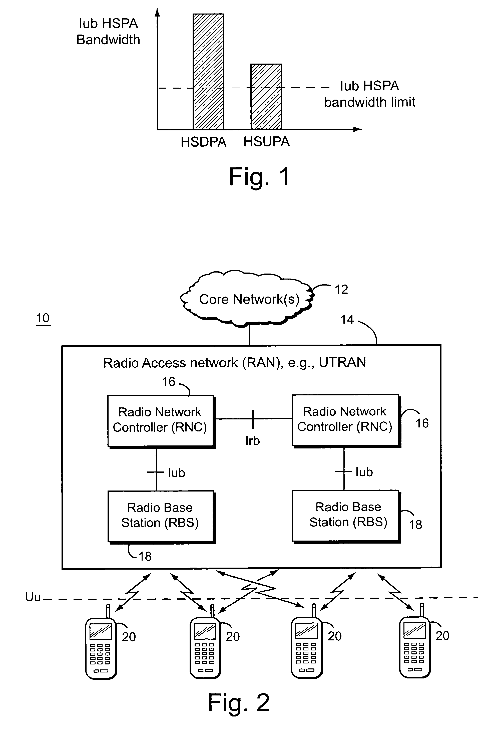
Should the uplink enhanced bit rate over the radio interface significantly exceed the Iub uplink bandwidth, congestion will likely occur with long delays and possibly lost or otherwise corrupted data frames.

Method used


Image

  • Uplink congestion detection and control between nodes in a radio access network
  • Uplink congestion detection and control between nodes in a radio access network
  • Uplink congestion detection and control between nodes in a radio access network

Examples


Embodiment Construction

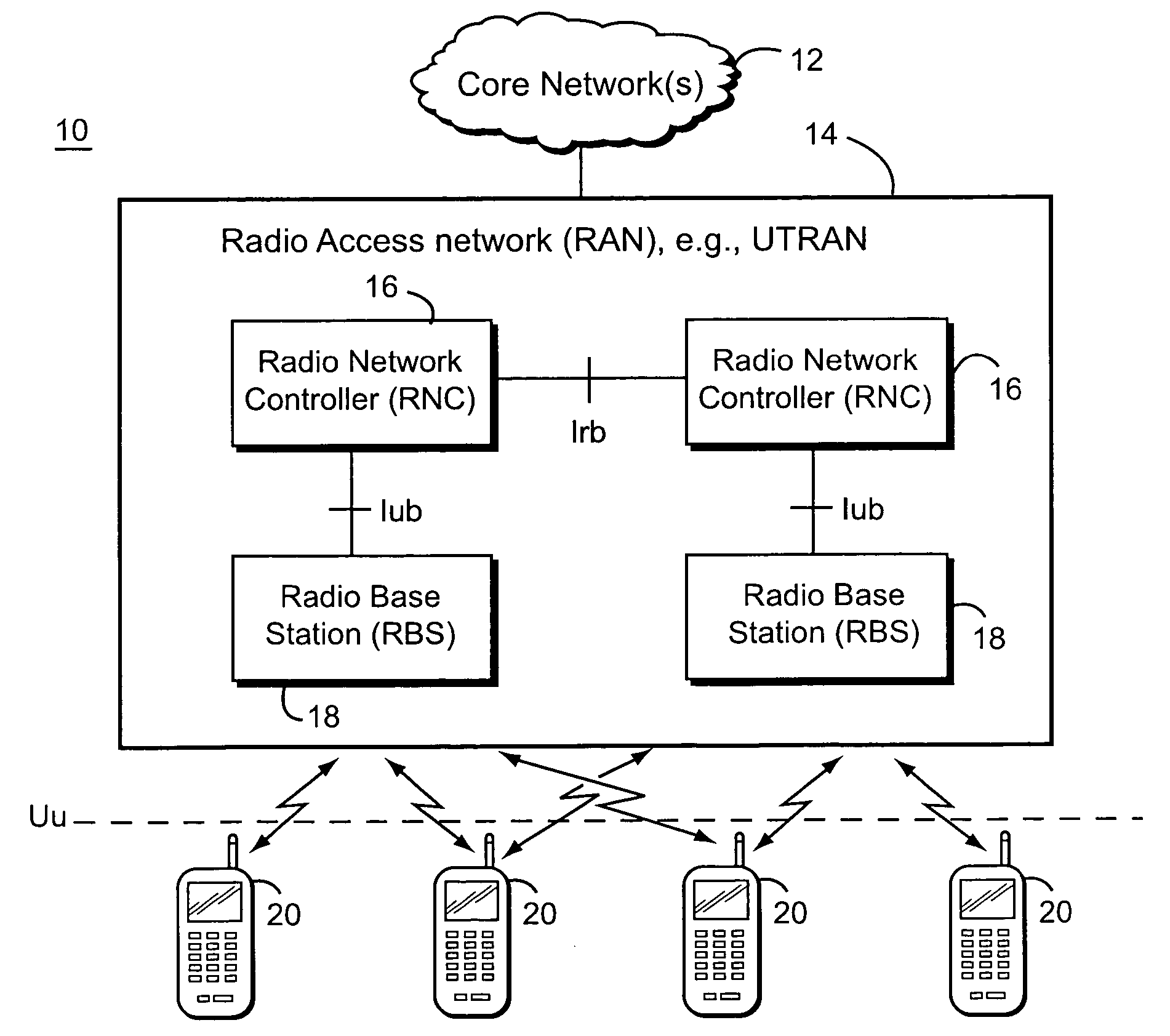
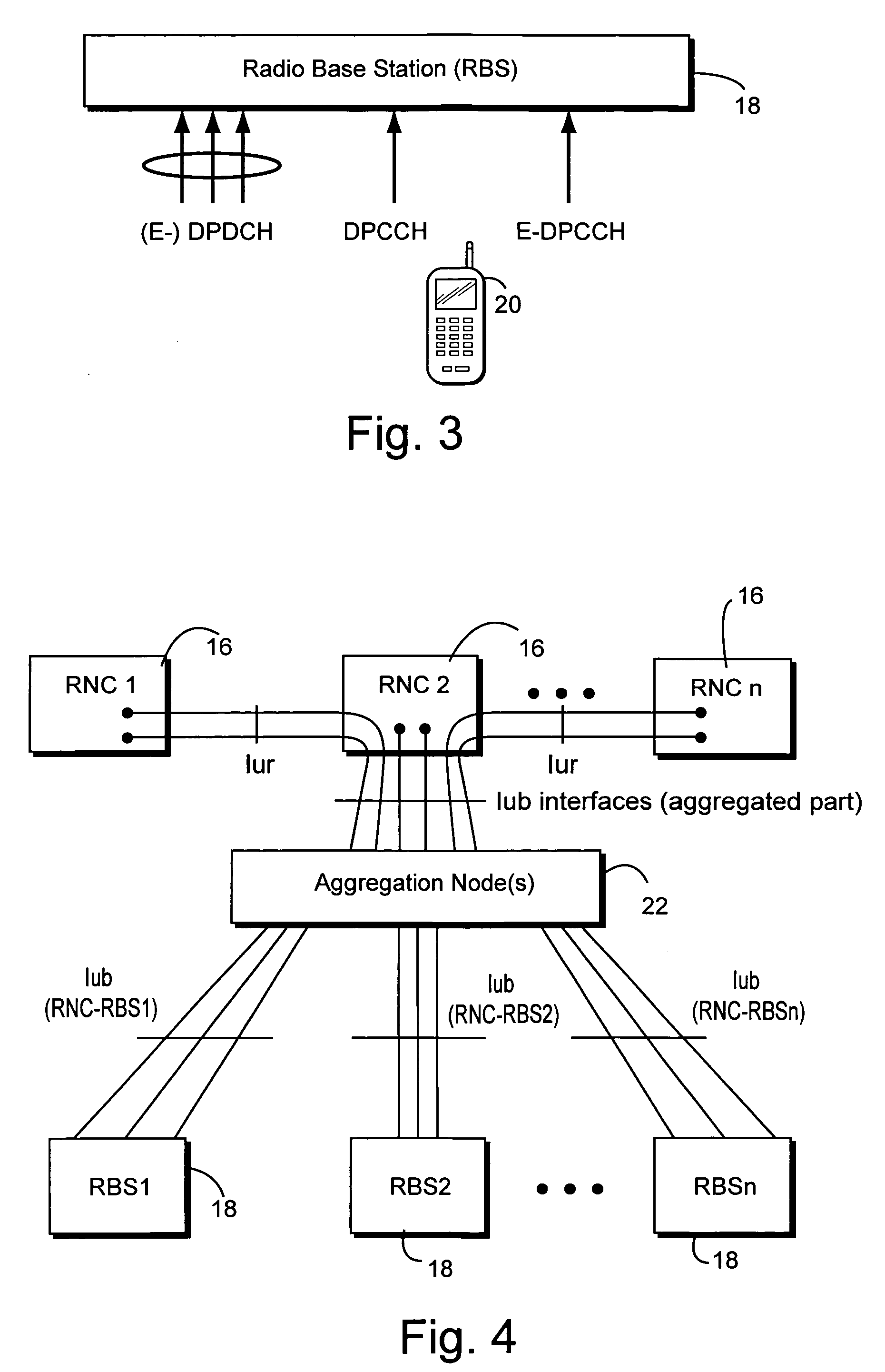
[0020]In the following description, for purposes of explanation and non-limitation, specific details are set forth, such as particular nodes, functional entities, techniques, protocols, standards, etc. in order to provide an understanding of the described technology. For example, one advantageous applications is to enhanced uplink communications in accordance with 3GPP specifications. But other applications and other standards may be employed. It will apparent to one skilled in the art that other embodiments may be practiced apart from the specific details disclosed below. In other instances, detailed descriptions of well-known methods, devices, techniques, etc. are omitted so as not to obscure the description with unnecessary detail. Individual function blocks are shown in the figures. Those skilled in the art will appreciate that the functions of those blocks may be implemented using individual hardware circuits, using software programs and data in conjunction with a suitably prog...


PUM


Abstract

Congestion in a radio access network (RAN) associated with transporting uplink information originating from one or more mobile terminals is detected. That detected RAN congestion is reduced using any suitable technique (several examples are described) and may be implemented in one or more nodes in the RAN. One advantageous (but non-limiting) application is to a RAN that supports high speed uplink packet access (HSUPA) and / or one or more enhanced uplink dedicated channels (E-DCHs).

Description

TECHNICAL FIELD[0001]The technical field relates to mobile data communications, and more particularly, to regulating uplink communications from mobile radio terminals in a radio access network.BACKGROUND AND SUMMARY[0002]There is an ever increasing demand for wireless communication devices to perform a variety of applications. Some of those applications require substantial bandwidth. For example, next generation wireless communication systems may offer high speed downlink packet access (HSDPA) and high speed uplink packet access (HSUPA) to provide enhanced data rates over the radio interface to support Internet access and multimedia type applications.[0003]The enhanced uplink concept currently being considered in the 3rd Generation Project Partnership (3GPP) intends to introduce substantially higher peak data rates over the radio interface in the uplink direction. Enhanced uplink data communications will likely employ fast scheduling and fast hybrid automatic repeat request (HARQ) w...

Claims


Application Information

Patent Timeline
Patent Type & Authority Patents(United States)
IPC IPC(8): G01R31/08G06F11/00G08C15/00H04J1/16H04L1/00H04L12/26H04L12/28H04W24/00H04W28/10
CPCH04L47/12H04L47/14H04W28/0284H04W28/10H04W28/0289H04W28/0236H04W36/22H04W72/0433H04W28/0205H04W24/00H04W88/12H04W88/08H04W8/04H04W28/0247H04W28/04H04W28/18H04W72/29
Inventor S{DOT OVERLUNDH, PETER
Owner LENOVO INNOVATIONS LTD HONG KONG
Learn More