
Detector array and device using the same

a technology of detector array and array, which is applied in the direction of material analysis using wave/particle radiation, instruments, applications, etc., can solve the problems of false discrimination results, negative impact on discrimination accuracy, severe defection, etc., to suppress false discrimination results, accurate detection, and improve the accuracy of dual-energy methods in discriminating materials

Inactive Publication Date: 2010-05-25
TSINGHUA UNIV +1
View PDF31 Cites 38 Cited by
  • Summary
  • Abstract
  • Description
  • Claims
  • Application Information

AI Technical Summary

Benefits of technology

[0005]In view of the above problem with the prior art, the present invention is accomplished. It is an object of the present invention to provide a detector array and a material discrimination system using this detector array, which can suppress discrimination errors occurring at the edge of the inspected object during the process of object inspection utilizing rays alternately generated.
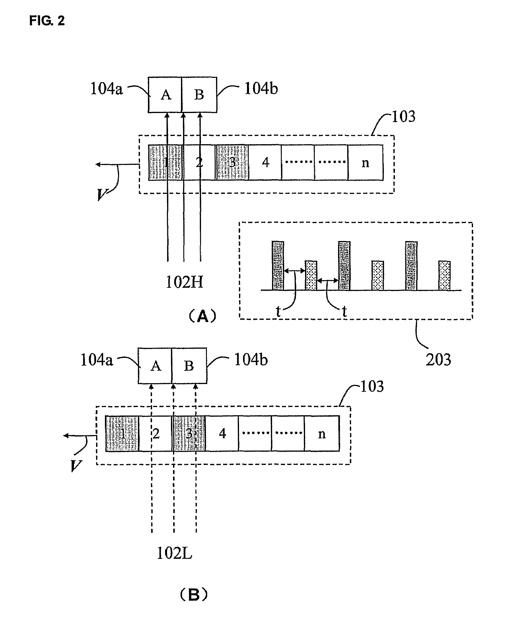
[0021]It is possible to make the ray beams having high and low energy levels interact with the object at the same position and realize accurate detection by utilizing the above detector array to detect the penetrating rays as well as by using dislocation matching. Meanwhile, since the distance between the first linear array and the second linear array is determined based on the moving speed of the inspected object and the time interval between the generation of rays having high and low energy levels by the radiation source, the rays interacting with the inspected object at the same part are ensured to be detected, thereby improving the accuracy of the dual-energy method in discriminating material and suppressing the false discrimination result at the edge of the inspected object. Because the distance between the first linear array and the second linear array is adjustable, the moving speed of the inspected object is variable. Therefore, the requirement for the moving speed of the inspected object is decreased. Moreover, since the first linear array and the second linear array simultaneously collect signals, the detective area is equivalently increased. On the other hand, the small section of the individual scintillator ensures to detect objects with high detection precision and obtain detailed detective images.

Problems solved by technology

However, when the alternately generated X-rays having high and low energy spectra are utilized to scan an object, a severe defection occurs as follows.
This will have a negative impact on the discrimination accuracy, especially at the edge of the inspected object where the rays having two energy levels may interact with different objects, thereby incurring a false discrimination result.
This method severely limits the efficiency of object inspection and can't solve the false discrimination occurring at the edge of the object.

Method used


Image

  • Detector array and device using the same
  • Detector array and device using the same
  • Detector array and device using the same

Examples


Embodiment Construction

[0026]Hereafter, an embodiment of the present invention is described in detail with reference to the drawings.

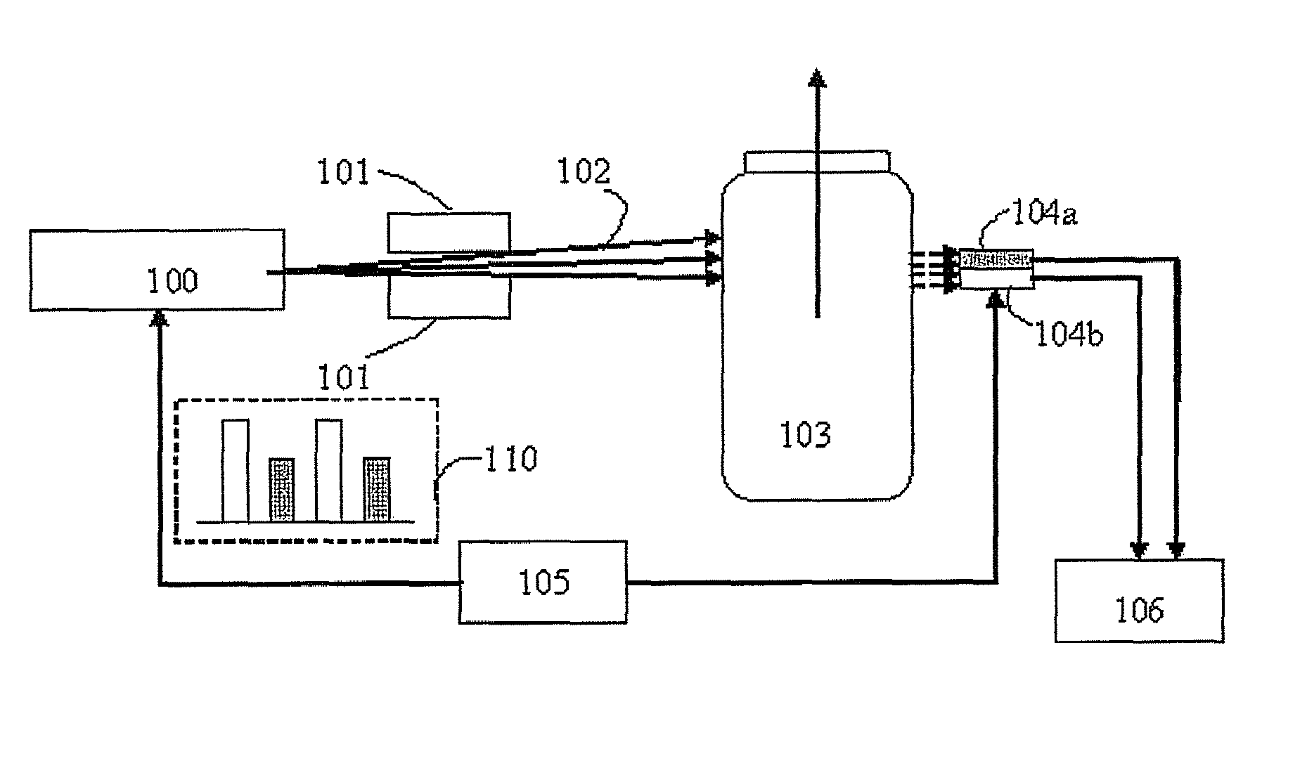
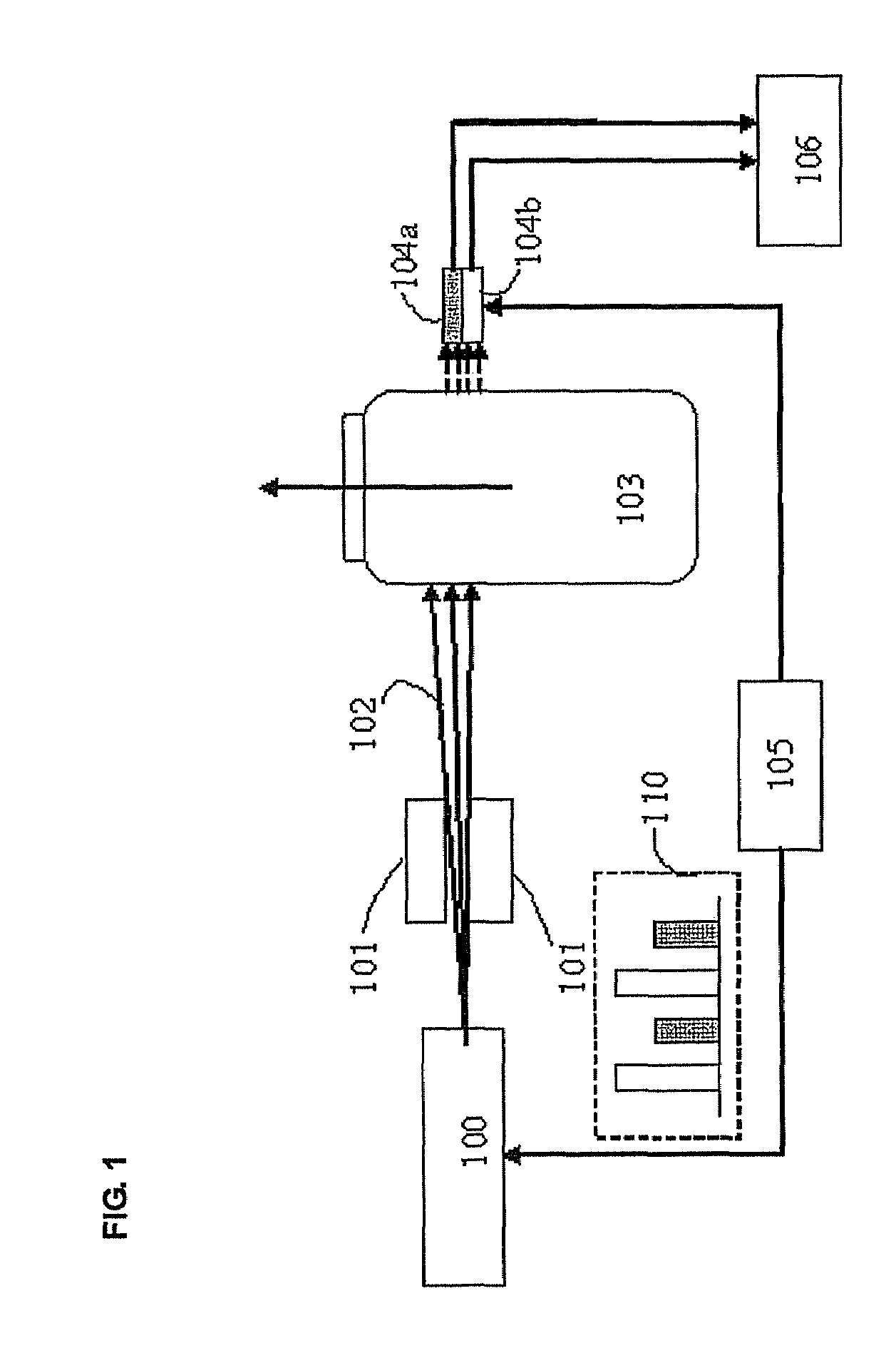
[0027]FIG. 1 is the schematic view of the material discrimination system using a detector array according to an embodiment of the present invention.

[0028]As shown in FIG. 1, the detector array including the first linear array 104a and the second linear array 104b is used to collect the dual-energy rays generated alternately by a radiation source. The radiation source 100 can alternately generate radiations such as X-rays. The synchronization control part 105 provides a synchronization signal 110 for the radiation source 100 and the first and second linear arrays 104a and 104b to make the radiation source 100 alternately generate high- and low-energy-level rays at the timing of the synchronization signal 110.

[0029]A fan-shaped planar radiation is obtained after the rays 102 generated by the radiation source 100 pass through the collimator 101. As shown in FIG. 1, the inspecte...


PUM


Abstract

Disclosed is a detector array comprising a first linear array for detecting a first ray and a second ray which penetrate through a first plurality of parts of the inspected object to acquire first values and second values for the first plurality of parts, wherein the second ray is alternately emitted with the first ray; and a second linear array arranged parallel to the first linear array for detecting the first ray and the second ray which penetrate through a second plurality of parts of the inspected object to acquire third values and fourth values for the second plurality of parts, wherein the first plurality of parts is partly identical to the second plurality of parts. With the detector array, the efficiency and material discrimination accuracy can be improved in the scanning inspection of the inspected object by use of alternate dual-energy rays.

Description

FIELD OF THE INVENTION[0001]The present invention relates to a detector for radiograph imaging of an object, and more particularly, to a detector array and a device using the same, which can eliminate error and inaccuracy of material discrimination at the edge occurring during the process of the object inspection using alternately generated rays, and can improve the efficiency of scanning inspection by multiples.BACKGROUND OF THE INVENTION[0002]The present application claims priority of Chinese patent application Serial No. 20061001 1943.X, filed May 19, 2006, the content of which is hereby incorporated by reference in its entirety.[0003]As the requirement for a security inspection system such as at Customs is constantly increased, the relevant technology has been widely applied as in U.S. Pat. No. 5,044,002, in which X-rays having two different energy levels are utilized to perform non-destructive inspection on an object while the material of the object is identified. Recently, the...

Claims


Application Information

Patent Timeline
IPC IPC(8): G01N23/087
CPCA61B6/482G01V5/0041G01N23/087G01N2223/5015G01V5/224G01N23/083G01V5/20
Inventor WANG, XUEWUCHEN, ZHIQIANGLI, YUANJINGZHONG, HUAQIANGZHANG, QINGJUNZHAO, SHUQING
Owner TSINGHUA UNIV
Learn More