Cable fault detection

a fault detection and cable technology, applied in the direction of electric devices, process and machine control, nuclear elements, etc., can solve the problems of power outages, circuit components can be prone to shorts or otherwise abnormally low impedance connections between two or more phases, failure or degradation of the insulation used,

Active Publication Date: 2010-05-25
HITACHI ENERGY SWITZERLAND AG
View PDF19 Cites 39 Cited by
  • Summary
  • Abstract
  • Description
  • Claims
  • Application Information

AI Technical Summary

Problems solved by technology

Unfortunately, however, these circuit components can be prone to shorts or otherwise abnormally low impedance connections between two or more phases or between one or more phases and ground.
These faults can be caused by a number of factors, including human error (e.g., accidentally cutting or striking a cable), climatologic conditions (e.g., precipitation, seismic activity, or lightning strikes), animal activity, and failure or degradation of the insulation used in the feeder equipment.
Moreover, such faults can lead to power outages, which are inconvenient for the affected customers and which can be expensive for the electric utility involved.
One category of fault is that of self-clearing faults, particularly in cable systems.
While self-clearing faults can have any number of root causes, they typically have insufficient duration to trip the relevant protective device.
As the situation deteriorates, the frequency and severity of these faults tend to worsen with time, culminating in an eventual cable failure and a resultant power outage.
One consequence of this relay-centric architecture is that the apparatus is relatively poorly integrated with the substation automation (SA), distribution automation (DA), feeder automation (FA), or other automation system.
Moreover, the apparatus requires the use of a specialized hardware platform which must be closely coupled to the protective relay, and the detection techniques have been relatively unsophisticated and prone to noise and outliers.

Method used


Image

  • Cable fault detection
  • Cable fault detection
  • Cable fault detection

Examples


Embodiment Construction

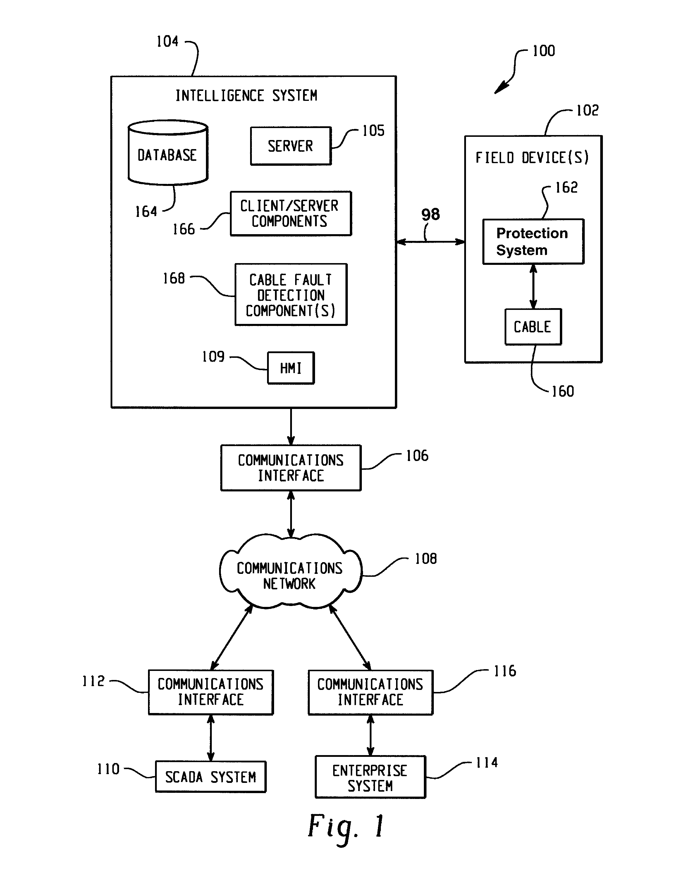
[0015]With reference to FIG. 1, a substation 100 includes a plurality of field devices 102, a substation intelligence system 104 and a communication interface 106. The field devices 102 include transformers, capacitors, circuit breakers, intelligent electronic devices (IEDs) and other equipment and assets as are typically encountered in the substation environment. In the present example, the field devices 102 include one or more cables 160 such as transmission or feeder cables and associated protection systems 162.

[0016]The field devices 102 are operatively connected to the substation intelligence system 104 by a communication link 98, which may be a physical hardwired link, a cellular link, a modem or telephone line link, an Internet link or any other wireless or wide area or shared local area network link. Depending on the architecture of a given system, the intelligence system 104 may function as one or more of a substation automation system, a feeder automation system, or a dist...


PUM


Abstract

A cable fault detection component (168) receives input data indicative of a fault in an electrical power system. The component (168) analyzes the input data to determine if the fault is indicative of a temporary or self-clearing cable fault and generates corresponding output data (276). In one implementation, the cable fault detection component (168) is implemented as a software module which operates on a computer (105) of a substation intelligence system (104).

Description

CROSS-REFERENCE TO RELATED APPLICATION[0001]This application is a continuation-in-part of U.S. patent application Ser. No. 11 / 555,429 filed on Nov. 1, 2006, which is hereby incorporated by reference in its entirety.BACKGROUND OF THE INVENTION[0002]The present application relates to fault detection in electrical power transmission and distribution systems. It finds particular application to the detection and analysis of faults in underground cables and other conducting medium used in the underground and overhead power distribution feeders.[0003]Underground and overhead feeders are a key component in the transmission and distribution of electrical power. Unfortunately, however, these circuit components can be prone to shorts or otherwise abnormally low impedance connections between two or more phases or between one or more phases and ground. These faults can be caused by a number of factors, including human error (e.g., accidentally cutting or striking a cable), climatologic condition...

Claims


Application Information

Patent Timeline
Patent Type & Authority Patents(United States)
IPC IPC(8): G01R31/00G01R31/58
CPCG01R31/024G01R31/021G01R31/58
Inventor STOUPIS, JAMESMADWESH, AJAY C.LUBKEMAN, DAVIDMOUSAVI, MIRRASOUL
Owner HITACHI ENERGY SWITZERLAND AG
Why Eureka
Try Eureka