Scale factor measurement for mems gyroscopes and accelerometers

a technology of accelerometer and scale factor, which is applied in the direction of acceleration measurement using interia forces, instruments, devices using electric/magnetic means, etc. it can solve the problems of low accuracy, low accuracy, and relatively sensitiveness of mems inertial instruments, so as to reduce the sensitivity of cross-axis rotation rate inputs and minimize error torques

Inactive Publication Date: 2010-06-01
MILLI SENSOR & ACTUATOR SYST
View PDF6 Cites 13 Cited by
  • Summary
  • Abstract
  • Description
  • Claims
  • Application Information

AI Technical Summary

Benefits of technology

[0004]The G2-Gyroscope is a Coriolis gyroscope where the drive and output sense motions are angular oscillations. Its structure is generally planar and composed of two members: a Gyro Member and a Drive Member. The Gyro Member is the gyro. The Drive Member supports the Gyro Member above the substrate and is used to oscillate the Gyro Member about the Drive Axis, without applying direct actuation to the Gyro Member. Under rotation rate input, the Gyro Member responds by oscillating about the Output Axis (orthogonal to the Drive Axis). The Input Axis and Drive Axis are orthogonal to each other and lie in the plane of the gyroscope. The Output Axis is aligned normal to the plane. An attribute of this design is that the Gyro Member can be made symmetric about the Output Axis and therefore reduce sensitivity to cross-axis rotation rate inputs. By using the Drive Member to indirectly drive the Gyro Member, error torques are minimized.
[0009]This invention further relates to the indirect drive of the Gyro Member through a Drive Member (DM), to which the Gyro Member is attached. The purpose is to minimize unwanted drive of the Gyro Member about the Output Axis (quadrature source).
[0011]This invention also relates to the alternate design where the Gyro Member is larger and driven directly to oscillate about the Drive Axis. The larger size of the Gyro Member increases gyroscope sensitivity. In this case, the member that supports the gyro member relative to the substrate is not driven, and thus is not really a “Drive Member.” This member may thus be generally termed, for some preferred embodiments, a “support member.”
[0013]This invention also relates to the monolithic construction of the gyro with built-in scale factor measurement capability to minimize structural instability. The structure is electrically connected to ground.
[0015]This invention also relates to the ability to measure scale factor at any time or continuously, including during the period of instrument operation. This capability eliminates the need to conduct extensive testing to fully calibrate the instrument at every state of the environment so that compensation algorithms may be used to correct the instrument during operation. This capability also considers that the calibrations may not remain correct over time.
[0016]This invention helps to maintain the accuracy of the MEMS instrument and greatly reduce the cost of calibrations.

Problems solved by technology

Due to their very small size, and materials and methods of construction, such MEMS inertial instruments are relatively sensitive to ambient temperature and other environmental factors.
These sensitivities makes them relatively unstable.
This testing is time consuming and expensive, and also may not anticipate every possible condition that the instrument may be exposed to, which can lead to errors.

Method used


Image

  • Scale factor measurement for mems gyroscopes and accelerometers
  • Scale factor measurement for mems gyroscopes and accelerometers
  • Scale factor measurement for mems gyroscopes and accelerometers

Examples


Embodiment Construction

Design Guidelines

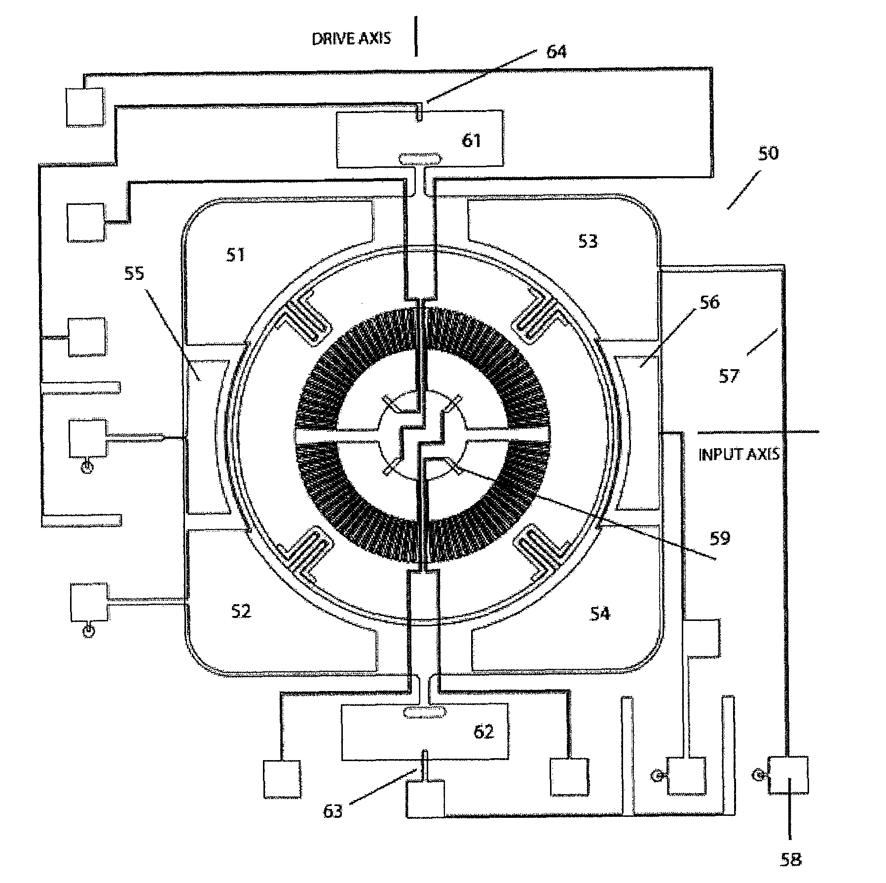
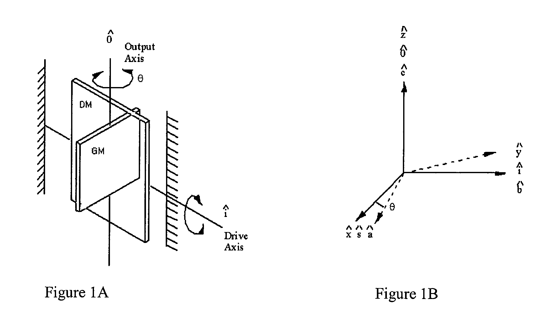
[0048]The design of one preferred embodiment of the invention incorporates:[0049]a symmetric disk (Gyro Member or “GM” herein) in the plane of the instrument that is driven to oscillate about an axis in the plane (Drive Axis), by the use of an outer structure, the Drive Member; the gyro output motion is the oscillation of the disk about the axis normal to the plane (Output Axis); the purpose of the symmetric disk is to reduce sensitivity to cross-axis rotation rate,[0050]the disk is mounted to the Drive Member (DM) so that the drive of the disk about the Drive Axis is accomplished through the DM structure and actuation is not applied directly to the disk itself; the purpose is to minimize the inadvertent drive of the disk about the Output Axis,[0051]the Drive Member is connected with a pair of torsional flexures to bonding pads attached to the substrate,[0052]a mesa between the bonding pads and the substrate provides the working gap that allows motion of the GM and ...


PUM


Abstract

An inertial instrument such as an accelerometer or gyroscope having scale factor functionality, and that lies generally in a plane. The gyro detects rotation rate about a gyro input axis. The gyroscope has a substrate, a generally planar scale factor gimbal flexibly coupled to the substrate such that it is capable of oscillatory motion about the input axis, a generally planar support member coplanar with and flexibly coupled to the scale factor gimbal such that the support member is capable of oscillatory motion about a drive axis that is orthogonal to the input axis, and a generally planar gyro member coplanar with and flexibly coupled to the support member such that it is capable of rotary oscillatory motion relative to the support member about an output axis that is orthogonal to the plane of the members. There are one or more first drives for oscillating the support member about the drive axis, and one or more second drives for oscillating the scale factor gimbal about the input axis. One or more gyro output sensors that detect oscillation of the gyro member about an output axis that is orthogonal to both the input axis and the drive axis.

Description

CROSS REFERENCE TO RELATED APPLICATION[0001]This application is a continuation in part of application Ser. No. 11 / 426,368 filed on Jun. 26, 2006, now U.S. Pat. No. 7,406,867 the disclosure of which is incorporated herein by reference. This application also claims priority of Provisional patent application Ser. No. 60 / 745,433, with a filing date of Apr. 24, 2006, the disclosure of which is incorporated herein by reference.FIELD OF THE INVENTION[0002]This invention relates to MEMS inertial instruments, including gyroscopes and accelerometers.BACKGROUND OF THE INVENTION[0003]Micro-electro-mechanical systems (MEMS) gyroscopes and accelerometers, such as disclosed in U.S. Pat. Nos. 6,725,719 and 6,859,751, are generally planar instruments. Due to their very small size, and materials and methods of construction, such MEMS inertial instruments are relatively sensitive to ambient temperature and other environmental factors. These sensitivities makes them relatively unstable. Accordingly, it...

Claims


Application Information

Patent Timeline
Patent Type & Authority Patents(United States)
IPC IPC(8): G01P9/04G01C19/00G01C25/00
CPCG01C19/5719G01P15/097G01P15/0802G01P2015/0814
Inventor CARDARELLI, DONATO
Owner MILLI SENSOR & ACTUATOR SYST
Why Eureka
Try Eureka