Fuel cell vehicle having support frame which couples side frames in width direction of vehicle

a fuel cell and support frame technology, applied in the direction of vehicle sub-unit features, vehicle mounting, electrochemical generators, etc., can solve the problems of hydrogen leakage from the fuel cell or high-voltage current leakage, difficult to design or develop a vehicle suitable, and difficult to use a common frame (or platform) with vehicles employing an internal combustion engin

Inactive Publication Date: 2010-06-01
HONDA MOTOR CO LTD
View PDF62 Cites 58 Cited by
  • Summary
  • Abstract
  • Description
  • Claims
  • Application Information

AI Technical Summary

Benefits of technology

[0009]In light of the above circumstances, an object of the present invention is to provide a fuel cell vehicle for providing safety with respect to a vehicle collision.
[0016]In accordance with the above structure, in the area where the support frame is formed, deformation of the vehicle is prevented when a vehicle collision occurs. Therefore, it is possible to protect the fuel cell. In addition, the fuel cell and the motor are respectively arranged on the upper and lower sides of the support frame; thus, it is possible to prevent the fuel cell from being damaged by the motor which is forced toward the fuel cell.
[0019]Accordingly, when a front collision of the vehicle occurs, the motor can be guided toward a lower-back side of the support frame; thus, it is possible to reliably prevent the fuel cell from being damaged by the motor which is forced toward the fuel cell, and to provide a desired collision stroke with respect to the front collision of the vehicle.

Problems solved by technology

Therefore, it is difficult to use a common frame (or platform) with vehicles employing an internal combustion engine.
In addition, restrictions also occur in terms of design or convenient use of the vehicle, so that it is difficult to design or develop a vehicle suitable for individual use, and thus improvement with respect to such a problem has been required.
However, in the structure disclosed in H08-192639, the fuel cell is positively deformed so as to allow the side frame to absorb the collision energy, which may cause hydrogen leakage from the fuel cell or high-voltage current leakage.
Therefore, it is difficult to provide safety with respect to a vehicle collision.

Method used


Image

  • Fuel cell vehicle having support frame which couples side frames in width direction of vehicle
  • Fuel cell vehicle having support frame which couples side frames in width direction of vehicle
  • Fuel cell vehicle having support frame which couples side frames in width direction of vehicle

Examples


Embodiment Construction

[0032]Hereinafter, an embodiment in accordance with the present invention will be described with reference to the appended figures.

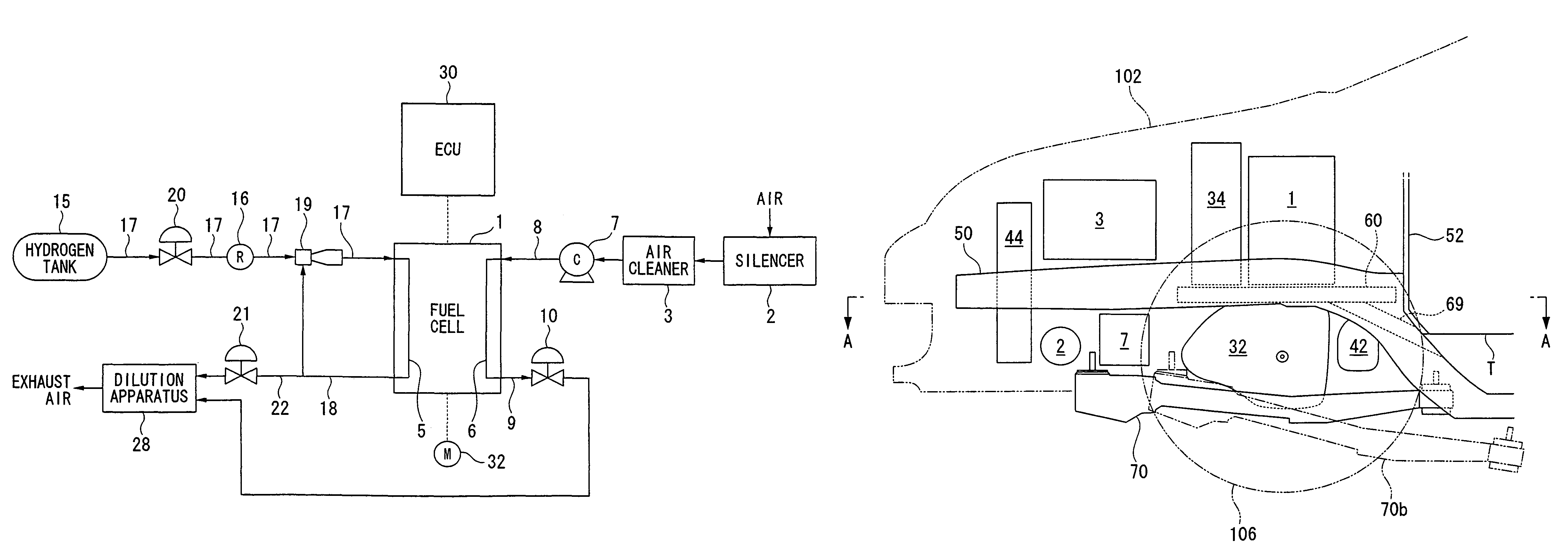
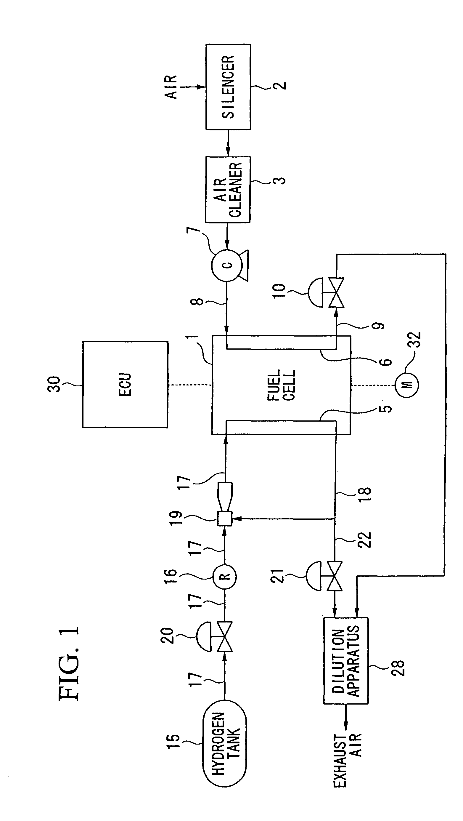
[0033]FIG. 1 is a diagram showing the general structure of a fuel cell system in a fuel cell vehicle. A fuel cell 1 generates electric power by way of an electrochemical reaction between reaction gases, and may be formed by stacking a plurality of unit cells, each having a structure in which a solid polymer electrolyte membrane (e.g., a solid polymer ion-exchange film) is interposed between an anode and a cathode. Hydrogen gas as a fuel gas is supplied to a fuel gas passage 5 toward the anode, while air (i.e., including oxygen) as an oxidant gas is supplied to an oxidant gas passage 6 toward the cathode. Accordingly, hydrogen ions generated at the anode by catalytic reaction move through the solid polymer electrolyte membrane to the cathode, and an electrochemical reaction occurs between the hydrogen ions and oxygen at the cathode, thereby generating ele...


PUM


Abstract

A fuel cell vehicle includes: a motor chamber provided in a front part of the vehicle; side frames extending on right and left sides of the vehicle in a front-to-back direction of the vehicle; a fuel cell; a motor for driving the vehicle, wherein the motor is driven using electric power generated by the fuel cell, and the fuel cell, the motor, and the side frames are installed in the motor chamber; and a support frame for coupling rear portions of the side frames with each other in a width direction of the vehicle, and for supporting the fuel cell installed on the support frame, wherein the motor is arranged below the support frame. The fuel cell vehicle may further include a guide member for guiding the motor toward a lower-back side of the support frame when a front collision of the vehicle occurs.

Description

BACKGROUND OF THE INVENTION[0001]1. Field of the Invention[0002]The present invention relates to a front structure of a fuel cell vehicle.[0003]Priority is claimed on Japanese Patent Application No. 2006-072882, filed Mar. 16, 2006, the content of which is incorporated herein by reference.[0004]2. Description of the Related Art[0005]Recently, fuel cell vehicles have been developed. The fuel cell vehicle has a fuel cell for generating electric power due to an electrochemical reaction between hydrogen as a fuel gas and oxygen as an oxidant gas, and runs by driving a motor using the generated power.[0006]In such a fuel cell vehicle, structural elements of the fuel cell are disposed under the floor in a central part of the vehicle, so as to provide safety in consideration of a vehicle collision (see, for example, Japanese Unexamined Patent Applications, First Publications Nos. 2004-122972 and 2003-182378). However, when arranging the fuel cell and the like under the floor of the vehicle...

Claims


Application Information

Patent Timeline
Patent Type & Authority Patents(United States)
IPC IPC(8): B60K5/00B60K1/04B60L11/18
CPCB60K1/00B62D21/152B60K11/04B60Y2306/01
Inventor SUZUKI, HIROYOSHI
Owner HONDA MOTOR CO LTD
Why Eureka
Try Eureka