
Exhaust system baffle apparatus

Inactive Publication Date: 2010-06-01
LAUGHLIN JAMES C
View PDF20 Cites 6 Cited by
  • Summary
  • Abstract
  • Description
  • Claims
  • Application Information

AI Technical Summary

Benefits of technology

[0011]It is a further object of an exemplary form of one or more embodiments of at least one invention described herein to provide an exhaust system which reduces the exhaust system sound volume while minimizing degradation of engine power.
[0014]It is a further object of an exemplary form of one or more embodiments of at least one invention described herein to provide a method of producing or modifying an exhaust system to produce an acceptable sound volume and to minimize degradation of engine power.

Problems solved by technology

Because exhaust systems may limit the horsepower of an engine, racing vehicles often employ exhaust systems which minimize any loss of horsepower.
As a result, racing exhaust systems tend to be excessively loud.
However, the diversity of sounds produced by such systems is limited.
However, unlike their professional counterparts, car enthusiasts often require their cars to be used for general transportation in addition to racing.
Unfortunately, such modifications may require custom bending of exhaust pipe and welding.
Such modifications are both labor intensive and expensive.

Method used


Image

  • Exhaust system baffle apparatus
  • Exhaust system baffle apparatus
  • Exhaust system baffle apparatus

Examples


Embodiment Construction

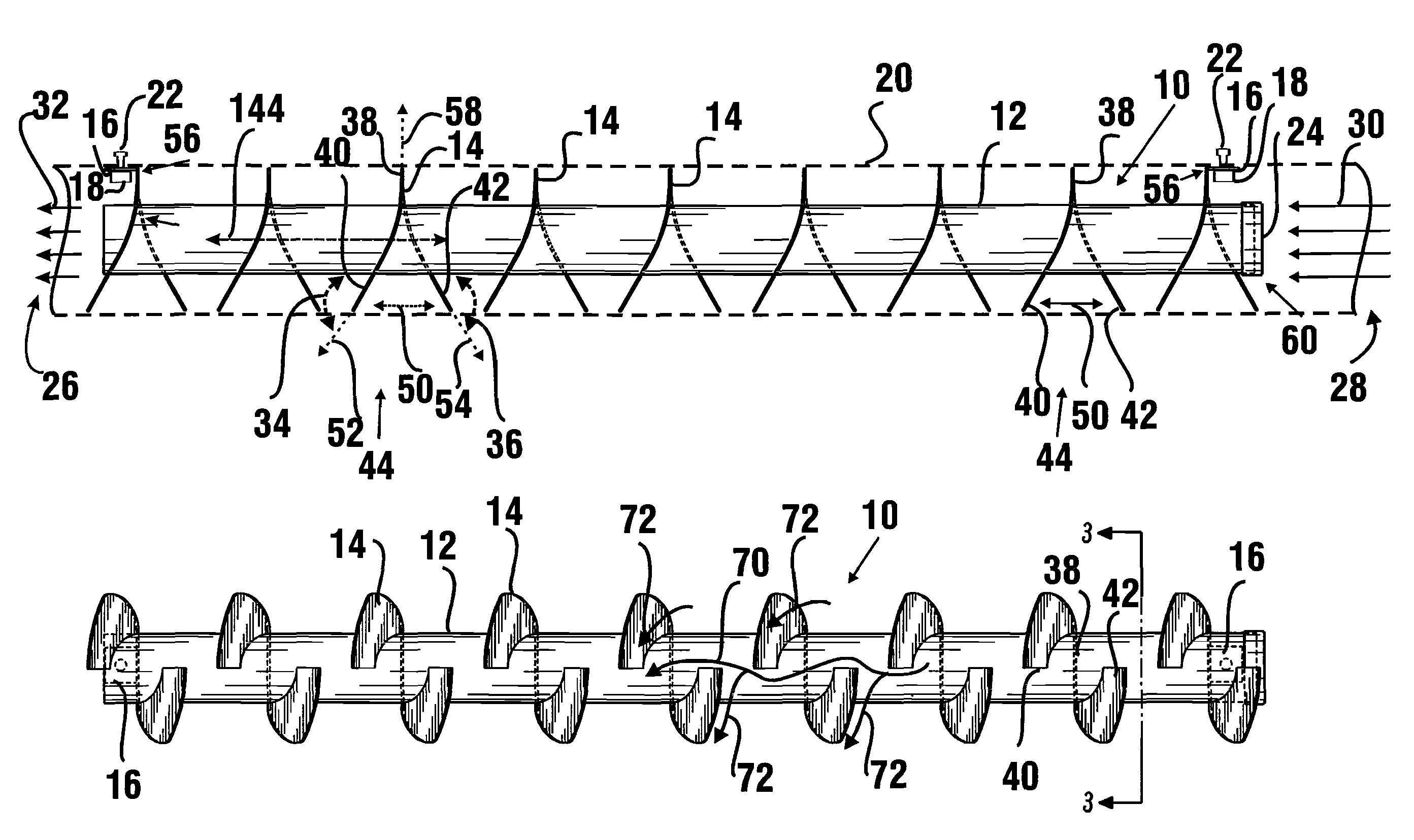
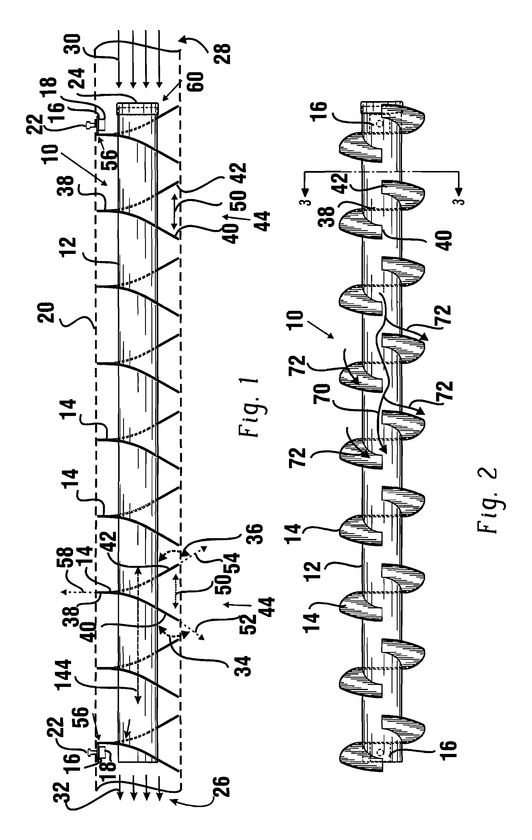
[0033]Referring now to the drawings and particularly to FIG. 1, there is shown therein a top plan view of an exhaust baffle apparatus 10 of an exemplary embodiment. The exemplary embodiment of the apparatus is adapted to be mounted within the interior portion of an exhaust pipe 20 of a vehicle with a combustion engine. When mounted within an exhaust pipe 20 in fluid communication with the headers of the engine, exhaust gases 30, 32 are operative to flow through the exhaust pipe adjacent the apparatus 10. The exemplary embodiment of the baffle apparatus 10 may be operative to both muffle the exhaust sound caused by the exhaust gas flows 30, 32 and produce a unique deep rumble tone.

[0034]For example, automobiles such as a General Motors 1967 Model Corvette, may include two side exhaust pipes with about 4 inch diameters. Exemplary embodiments of the baffle apparatus may be adapted to slide within each of the side exhaust pipes of the vehicle and be rigidly mounted to the inside walls o...


PUM


Abstract

An exhaust system baffle is provided comprising a tube and a plurality of radially extending flanges mounted in surrounding relation about the tube. Each flange includes a centrally positioned aperture and a slit that extends through the flange from the aperture to an outer edge of the flange. The tube extends through the apertures of the flanges. Each flange includes a first edge portion that bounds a first side of the slit. Each flange includes a second edge portion that bounds a second side of the slit opposite the first side of the slit. The opposed first and second edge portions of each flange are bent such that the opposed first and second edge portions are orientated to extend outwardly from the tube at angles that are each acute in opposed directions with respect to the central longitudinal axis of the tube.

Description

CROSS REFERENCE TO RELATED APPLICATIONS[0001]This application is a continuation-in-part of U.S. application Ser. No. 10 / 940,854 filed Sep. 13, 2004 which is a continuation-in-part of U.S. application Ser. No. 10 / 191,648 filed Jul. 8, 2002 (now U.S. Pat. No. 6,796,403), which claim the benefit of U.S. provisional application Ser. No. 60 / 316,728 filed Aug. 31, 2001. The disclosures of these applications are incorporated herein by reference.TECHNICAL FIELD[0002]Embodiments of at least one invention described herein relate to exhaust systems for moving vehicles. Specifically, embodiments relate to an exhaust system baffle apparatus which is operative to dampen the noise level of an exhaust system and produce a unique and desirable exhaust sound.BACKGROUND ART[0003]Exhaust systems for moving vehicles are well known. In general, exhaust systems provide a means for dampening or muffling the noise level associated with exhaust gases exiting a combustion engine. However, different types of v...

Claims


Application Information

Patent Timeline
IPC IPC(8): F01N1/12
CPCF01N1/12
Inventor LAUGHLIN, JAMES C.
Owner LAUGHLIN JAMES C
Features
  • Generate Ideas
  • Intellectual Property
  • Life Sciences
  • Materials
  • Tech Scout
  • Unparalleled Data Quality
  • Higher Quality Content
  • 60% Fewer Hallucinations
Learn More