Method and apparatus for forming in ground piles

a technology for ground piles and forming methods, applied in the field of methods, can solve the problems of weakening of piles, difficult extraction of apparatuses, and difficult extraction of grout, and achieve the effects of preventing necking, facilitating slide, and facilitating extraction

Inactive Publication Date: 2010-06-01
SJOGREN DAVID
View PDF21 Cites 9 Cited by
  • Summary
  • Abstract
  • Description
  • Claims
  • Application Information

AI Technical Summary

Benefits of technology

[0017]The interior mandrel is sized so as to easily slide along the interior annular space of the exterior casing. The apparatus is driven into the ground using known pile driving methods. During penetration into the soil, depending on the type of soil encountered and the type of pile to be formed, grout, air or water flows into the surrounding earth through aligned apertures on the exterior casing and the interior mandrel; this prevents necking, and provides a temporary frictionless medium to allow easy extraction of the apparatus. When the bottom of the apparatus reaches the desired depth, the interior mandrel is lifted out of phase relative to the exterior casing by raising it a predetermined distance relative to the exterior casing. This allows the pile forming materials to flow out the bottom of the apparatus. After lifting the interior mandrel a certain distances, the exterior casing is caused to be lifted.
[0018]The exterior casing maintains the integrity of hole as the pile forming material flows into the space created by the apparatus. Accordingly, the tendency to form voids and necks is substantially reduced. Additionally, because the apparatus comprises an exterior casing and an interior mandrel, the tubes may be made of thinner walled material than a conventional single mandrel, with the added advantage that the double tubes will be sturdier than a single mandrel having a thicker wall. This characteristic of double wall construction has been shown in performance and durability of double walled aluminum baseball bats when compared with single walled aluminum baseball bats.

Problems solved by technology

A significant problem with the gravity feed method is that the grout often cannot flow into the hole fast enough to keep up with its formation, thereby resulting in voids.
If soil or objects in the soil fall into these voids, the resultant pile diameter will neck down at the locations of the voids, weakening the pile.
However, pumping grout is also very problematic due to the inability to maintain a sufficient volumetric flow rate due to grout's the high viscosity.
All of the aforementioned approaches are subject to the problem of necking, because no exterior reinforcing casing is provided.
This adds to the cost of the pile.
However, this is also less than ideal because the exterior casing is permanently left in the ground, thereby increasing the costs for each pile.
Moreover, the aforementioned prior art devices suffer from lack of durability.
It is not uncommon for such mandrels, despite their sturdiness, to deflect during the driving process, which in turn will lead to inadequate pile formation or lost time.
In time, such mandrels may have to be scrapped because they have lost their straightness or because they cannot withstand the blows of the pile driver.
This is wasteful and expensive.
Additionally, the aforementioned devices do not accommodate the attachment of a vibrator without the need to halt the process.
This results in additional delay in the pile forming process and consequently results in additional costs for the installation of the pile.
This increases inventory costs, overhead and capital outlay.

Method used


Image

  • Method and apparatus for forming in ground piles
  • Method and apparatus for forming in ground piles
  • Method and apparatus for forming in ground piles

Examples


Embodiment Construction

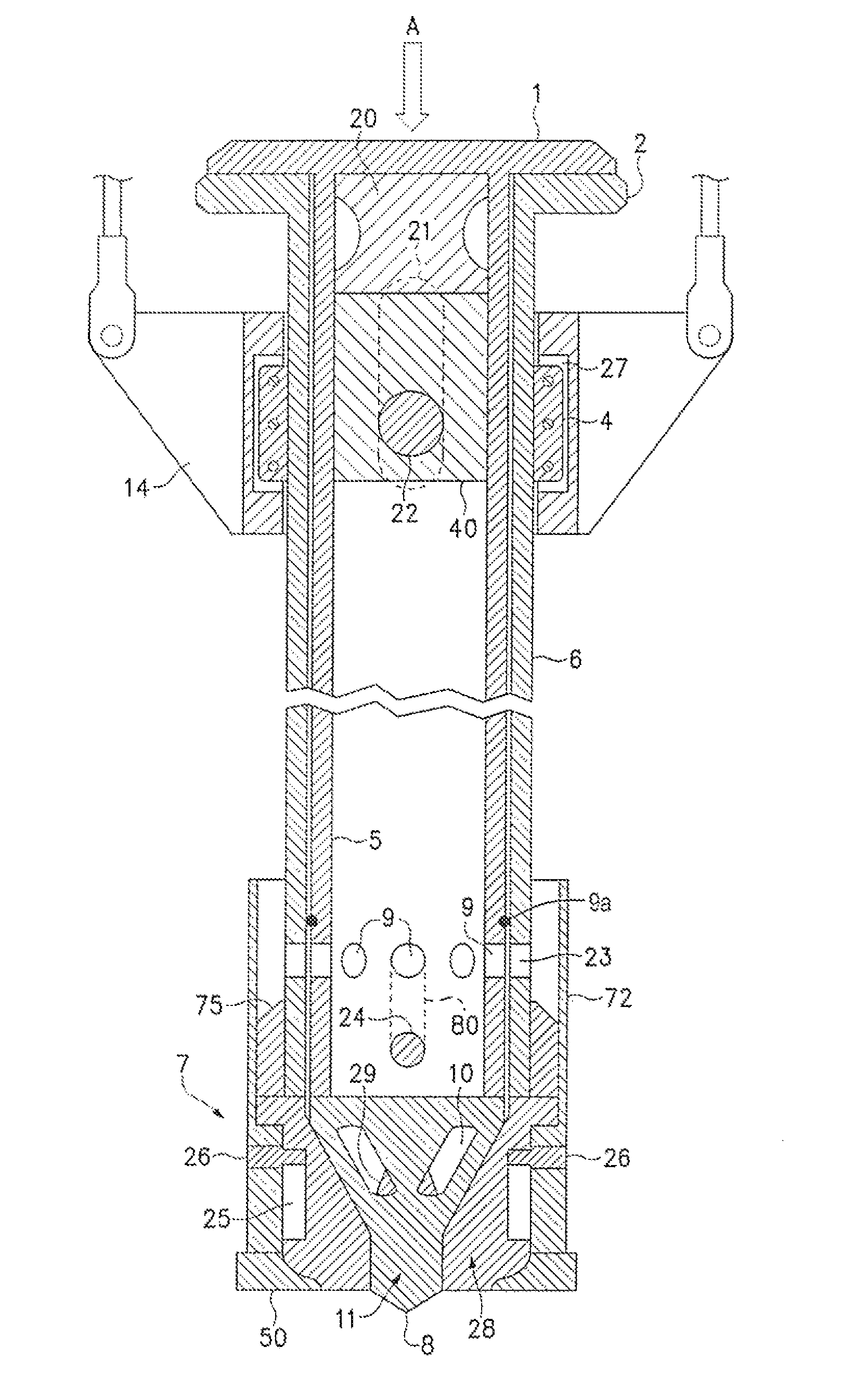
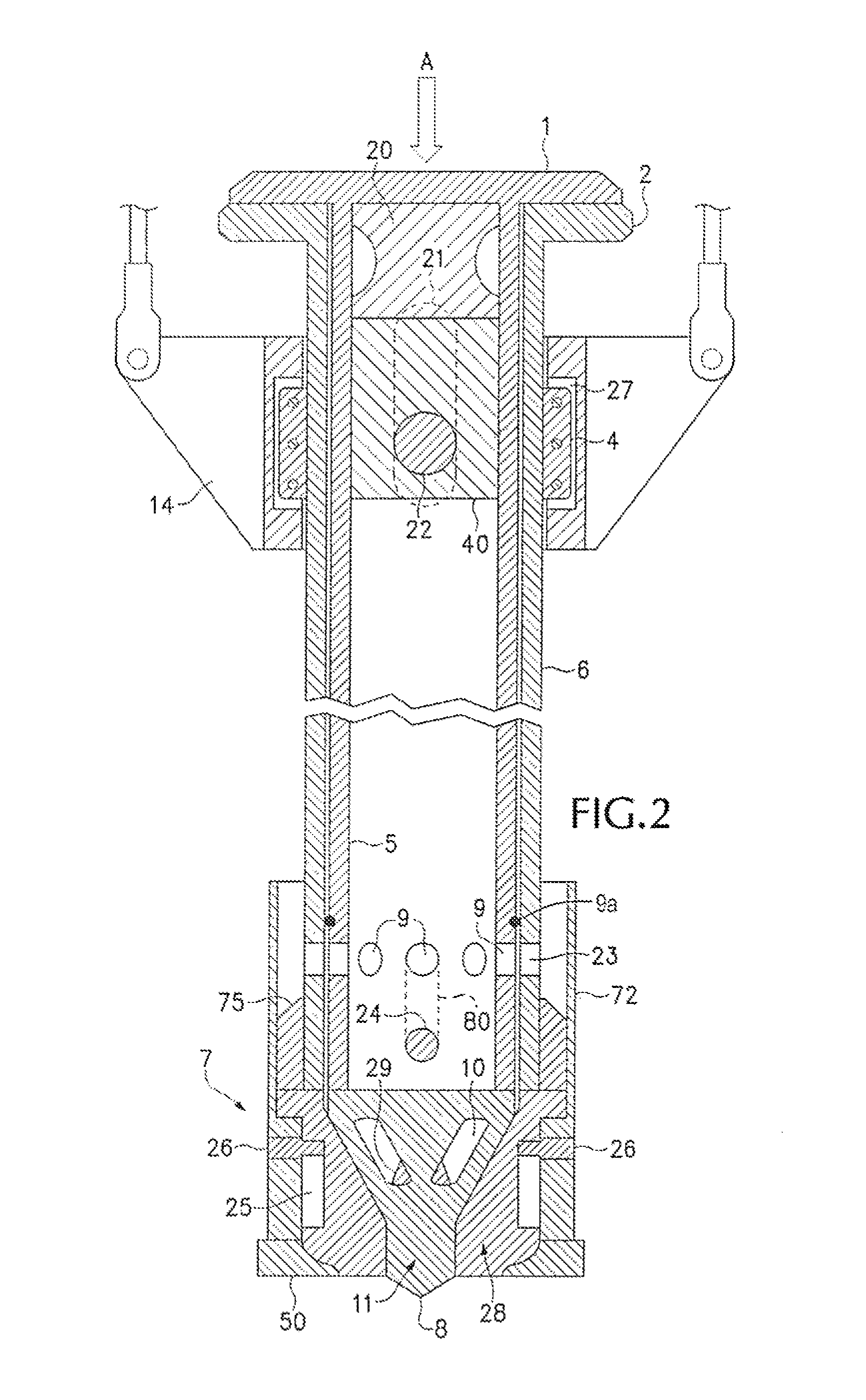
[0025]The invention comprises a pair of tubes with a first tube having a top and bottom. The bottom of the first tube comprises an open bottom and has an interior profile, the preferred profile is frusto-conical. The second tube having a top and bottom. The bottom of the second tube having a preferred exterior profile that is adapted to mate with the interior profile of the first tube, thereby sealing the open bottom of the first tube when the profiles come into contact with each other. Open slots are provided for in the profile of the second tube to allow transfer of material from the interior of the second tube out through the open bottom of the first tube when the profiles disengage. A more specific detail of the preferred embodiment is further discussed below.

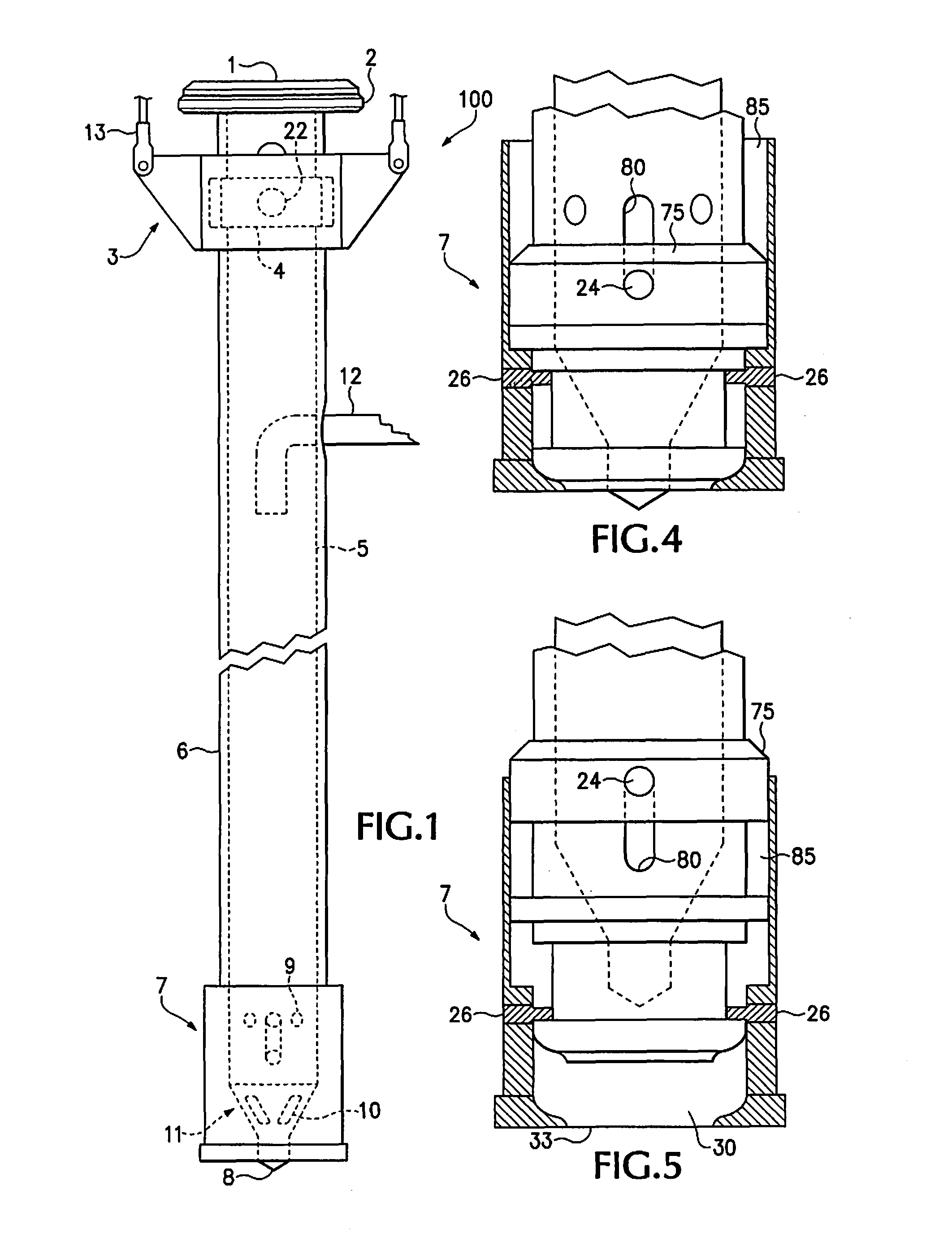
[0026]The preferred embodiment 100 comprises an exterior casing 6 and an interior mandrel 5. See, e.g, FIG. 1. The casing 6 and mandrel 5 may be of any cross section so long as mandrel 5 is able to fit slidably within casin...


PUM


Abstract

The present invention is an apparatus and a method for casting a cementitious or stone pile into the ground. The present invention comprises an exterior driving casing and an interior mandrel acting in cooperation to hold and deliver the pile forming material. A retrievable driving driving shoe is also disclose.

Description

CROSS-REFERENCE TO RELATED APPLICATIONS[0001]Not applicableSTATEMENT REGARDING FEDERALLY SPONSORED RESEARCH[0002]Not applicableSEQUENCE LISTING[0003]Not applicableBACKGROUND OF THE INVENTION[0004]1. Field of the Invention[0005]This invention relates to a method and apparatus for placing in-ground piles of either crushed stone or rock, grout or concrete, or some combination thereof.[0006]2. Description of Prior Art[0007]It has been known in the prior art, to make pilings from concrete by casting them in place in the ground. This is accomplished by driving an elongate mandrel, i.e., a hollow tube of a selected cross-sectional area, into the ground, filling the resultant hole with fluid grout, and then pulling the mandrel back out of the ground leaving the grout in place to cure. The holding ability of such a piling comes from end-bearing and from the friction which is created by the close contact between the pile's sidewalls and the surrounding soil. It has also become standard practi...

Claims


Application Information

Patent Timeline
Patent Type & Authority Patents(United States)
IPC IPC(8): E02B7/00
CPCE02D5/385
Inventor SJOGREN, DAVID
Owner SJOGREN DAVID
Why Eureka
Try Eureka