Wind power generator system and control method of the same

a generator system and wind power technology, applied in the direction of electric generator control, proportional-integral algorithms, machines/engines, etc., can solve the problems of short-time reduction in wind speed, and achieve the effect of suppressing output power fluctuation and generation efficiency reduction

Active Publication Date: 2010-06-01
MITSUBISHI HEAVY IND LTD
View PDF27 Cites 45 Cited by
  • Summary
  • Abstract
  • Description
  • Claims
  • Application Information

AI Technical Summary

Benefits of technology

[0005]Therefore, an object of the present invention is to provide a wind power generator system which suppresses output power fluctuation and generation efficiency reduction even when a transient wind null occurs.
[0007]The wind power generator system configured as stated above can suppress the output power fluctuation by using the rotational energy of the windmill rotor when the wind speed is reduced only for a short time. This is because the wind power generator system according to the present invention keeps the output power at the predetermined rated power in response to the pitch angle of the blade, when said rotational speed (ω) is reduced below said rated rotational speed. When it is determined from the pitch angle of the blade that the system is in a state in which the output power can be kept at the predetermined rated power, the output power is kept at the rated power, and this allows effectively extracting the rotational energy of the windmill rotor and suppressing the output power fluctuation and the power generation efficiency reduction.
[0014]The present invention provides the wind power generator system which can suppress the output power fluctuation and the generation efficiency reduction even when a transient wind null occurs.

Problems solved by technology

One issue for the wind power generator system is how to deal with occurrence of a transient wind null, that is, a short-time reduction in the wind speed.
This causes output power fluctuation and generation efficiency reduction.

Method used


Image

  • Wind power generator system and control method of the same
  • Wind power generator system and control method of the same
  • Wind power generator system and control method of the same

Examples


Embodiment Construction

[0027]A wind power generator system according to the present invention will be described hereinafter in detail with reference to the attached drawings.

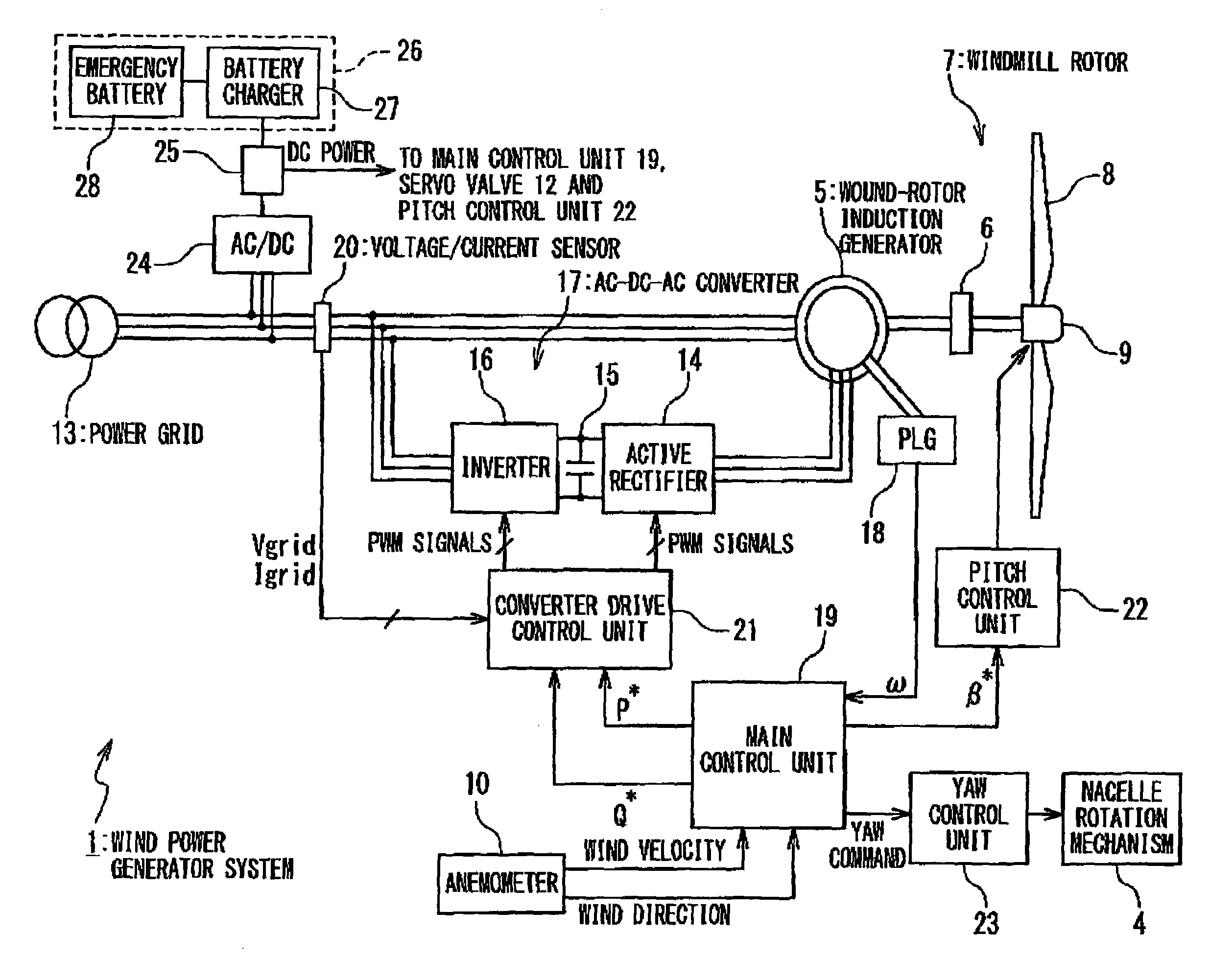
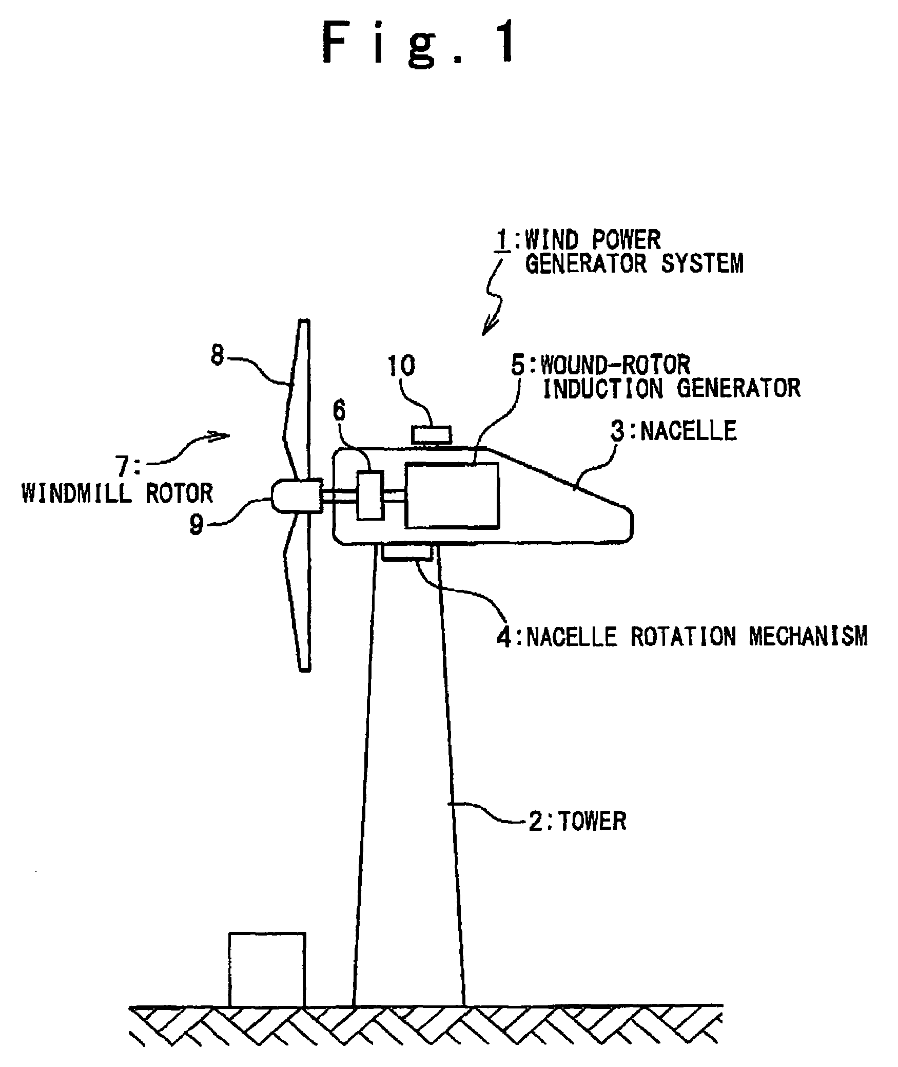
[0028]FIG. 1 is a side view showing the configuration of a wind power generator system 1 in one embodiment of the present invention. The wind power generator system 1 is provided with a tower 2 and a nacelle 3 provided on the top end of the tower 2. The nacelle 3 is rotatable in the yaw direction and directed to a desired direction by a nacelle rotation mechanism 4. Mounted in the nacelle 3 are a wound-rotor induction generator 5 and a gear 6. The rotor of the wound-rotor induction generator 5 is connected to a windmill rotor 7 through the gear 6. The nacelle 3 additionally includes an anemometer 10. The anemometer 10 measures the wind speed and the wind direction. As described later, the nacelle 3 is rotated in response to the wind speed and the wind direction measured by the anemometer 10.

[0029]The windmill rotor 7 includes blades 8...


PUM


Abstract

A wind power generator system including: a windmill rotor including a blade having a variable pitch angle; a generator driven by the windmill rotor; and a control unit controlling the output power of the generator and the pitch angle of the blade in response to the rotational speed of the windmill rotor or the generator. The control unit performs a first control in which the output power is controlled in accordance with a predetermined power-rotational speed curve until the rotational speed is increased to reach a predetermined rated rotational speed, and performs a second control in which the output power is controlled to a predetermined rated power when the rotational speed exceeds the rated rotational speed; the control unit is responsive to the pitch angle for maintaining a state of performing the second control is or for switching to a state of performing the first control, when the rotational speed is reduced below the rated rotational speed after the control unit is once placed into the state of performing the second control. This provides a wind power generator system which suppresses output power fluctuation and generation efficiency reduction when a transient wind null occurs.

Description

TECHNICAL FIELD[0001]The present invention relates to a wind power generator system and method for controlling the same, particularly, to control of the output power and the pitch angle of a wind power generator system adopting a variable-speed and variable-pitch control method.BACKGROUND ART[0002]One of the promising control methods for a wind power generator system is a variable-speed and variable-pitch control method, in which the rotational speed of the windmill rotor (that is, the rotational speed of the generator) is variable and the pitch angle of the blades is variable. Advantages of the variable-speed and variable-pitch control method include increased energy capture from the wind and decreased output fluctuation.[0003]With respect to the variable-speed and variable-pitch control method, it is of importance to optimize the control of the output power of the generator and the pitch angle of the blades. Japanese Translation of International Publication No. 2001-512804 disclos...

Claims


Application Information

Patent Timeline
Patent Type & Authority Patents(United States)
IPC IPC(8): F03D9/00H02P9/00
CPCF03D7/0224F03D7/028F03D7/042H02P9/48F03D7/0276H02P2101/15F05B2220/7064F05B2270/1033F05B2270/304F05B2270/32F05B2270/321F05B2270/322F05B2270/327F05B2270/705Y02E10/723Y02E10/725Y02E10/72
Inventor ARINAGA, SHINJIWAKASA, TSUYOSHIMATSUSHITA, TAKATOSHI
Owner MITSUBISHI HEAVY IND LTD
Why Eureka
Try Eureka