Computer resource management method in distributed processing system

a distributed processing and computer resource management technology, applied in the field of distributed processing system, can solve the problems of difficult to determine the timing of adding a new computer, the load factor is not equal in the computer, etc., and achieve the effect of uniform performan

Inactive Publication Date: 2010-06-01
HITACHI LTD
View PDF5 Cites 36 Cited by
  • Summary
  • Abstract
  • Description
  • Claims
  • Application Information

AI Technical Summary

Benefits of technology

[0006]According to an embodiment of the present invention, hardware information showing the type of the hardware constituting a computer resource and software information showing the type of software mounted in the computer resource are stored in the entry corresponding to each computer resource in a computer configuration table managed by the management computer. Furthermore, when a computer resource to be allocated to a certain job is determined, a computer resource that may be used for the job in the aftertime is selected and the job name is stored in the entry corresponding to the selected computer resource in the computer configuration table. More specifically, in addition to computer resources actually allocated to a job, a computer resource tentatively booked to be used for the job in the aftertime is provided. When it becomes necessary to additionally allocate a computer to the job, the tentatively booked computer resource is additionally allocated. If there is no computer resource tentatively booked for the job, a computer resource not booked for another job is allocated with priority. If a computer resource to be tentatively booked for a job is selected under the condition that it must have the same hardware type and software type as those of the computer resources allocated to the job, the computer resources which share the same job have uniform performance.
[0008]According to the present invention, the performance of the computer resources which share the same job can be equalized. Therefore, the timing for providing an additional computer can be easily determined by detecting the overload.

Problems solved by technology

Meanwhile, if the performance thereof is not uniform, the load factor is not equal in the computers.
Therefore, it becomes difficult to determine the timing for adding a new computer due to the overload.

Method used


Image

  • Computer resource management method in distributed processing system
  • Computer resource management method in distributed processing system
  • Computer resource management method in distributed processing system

Examples


first embodiment

[0028]An embodiment in which the present invention is applied to a distributed processing system that constitutes a data center will be described below.

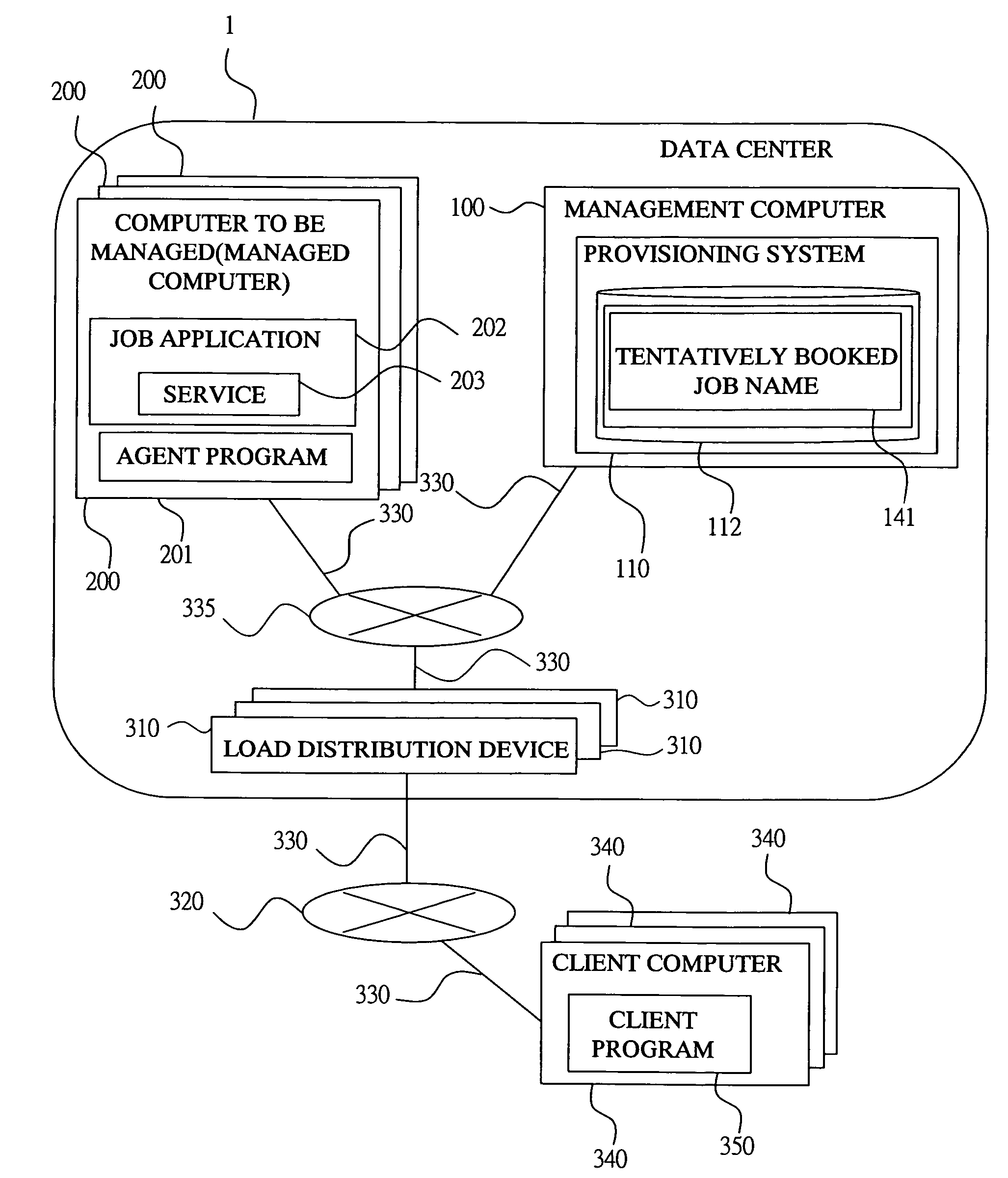
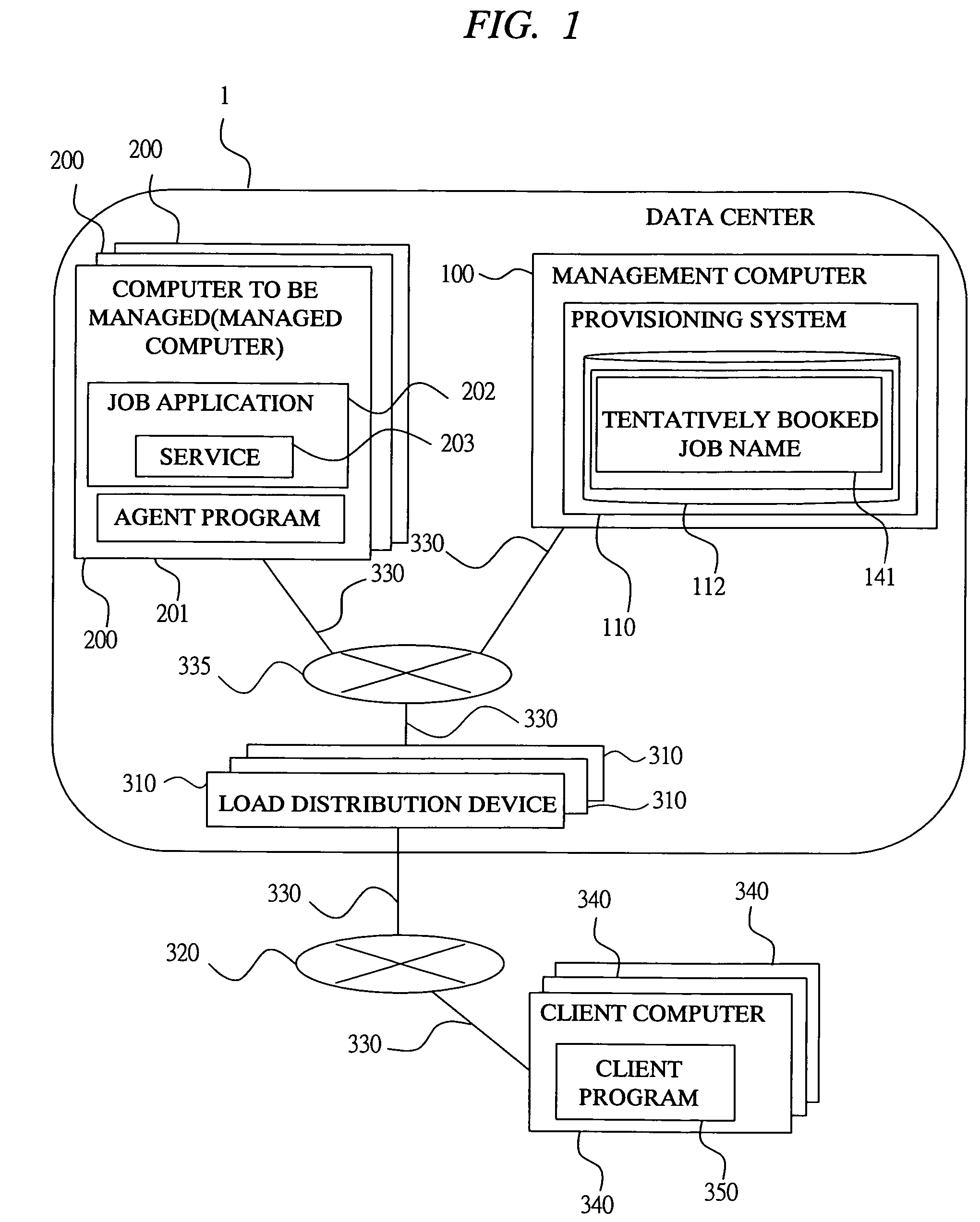
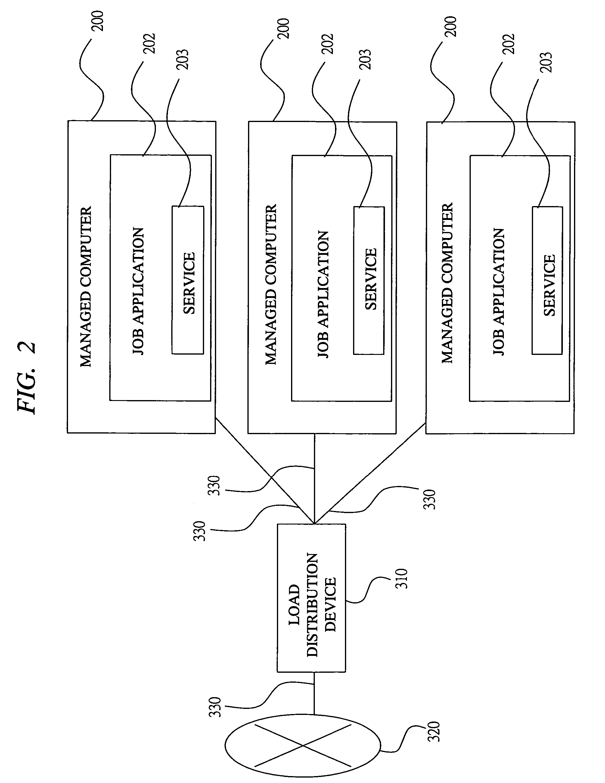
[0029]FIG. 1 is a diagram showing system configuration according to this embodiment. A data center 1 and a plurality of client computers 340 are connected via the Internet 320. Load distribution devices 310 in the data center 1 and the client computers 340 outside the data center 1 are connected to the Internet 320 via a network cable 330 so as to communicate with each other.

[0030]A client program 350 is operated on the client computer 340. The client program 350 accesses a service 203 provided by a job application 202 operated on a computer to be managed (hereinafter, also referred to as a managed computer) 200 in the data center 1 via the Internet 320 and the load distribution device 310 in the data center 1, and uses the service.

[0031]A management computer 100, a plurality of managed computers 200, a plurality of load distribution...

second embodiment

[0067]The second embodiment of the present invention obtained by partly modifying the first embodiment will be described below.

[0068]In the provisioning system of the second embodiment, an equalization spec conversion information storing region 190 shown in FIG. 18 is additionally provided to the provisioning system of the first embodiment (FIG. 3).

[0069]In the equalization spec conversion information storing region 190, a plurality of equalization spec conversion information 191 are registered. Of the pairs of the hardware information and the software information in the managed computers comprised of the items shown in FIG. 6, the hardware information and the software information including the items which require the definition of the range regarded as the same spec are registered in each of the equalization spec conversion information 191 by the manager of the data center. The hardware condition 192 and the software condition 193 in FIG. 18 are the hardware information and the sof...

third embodiment

[0071]In the third embodiment, an equalization process execution flag 165 is added to the entry corresponding to each job name of the job management table 160 described in the first embodiment (FIG. 7). The equalization process execution flag 165 shows whether or not the corresponding job is the job to which the equalization processing of FIG. 14 is executed. In the equalization processing of the first embodiment described with reference to FIG. 14, the range of the job name acquired in the process of acquiring the job name in Step 1400 is changed. More specifically, only the job name corresponding to the entry whose equalization process execution flag 165 is set to “true” is acquired, and the job name of the entry whose equalization process execution flag 165 is set to “false” is not acquired. In this embodiment, it is possible to specify whether or not the equalization process shown in FIG. 14 is executed for each job.


PUM


Abstract

The hardware information showing a type of hardware constituting the computer resource and the software information showing a type of software mounted in the computer resource are stored in the entry corresponding to each computer resource in the computer configuration table managed by a management computer. Further, when a computer resource allocated to a certain job is determined, a computer resource which may be used for the job in the aftertime is selected with reference to the hardware information and the software information, and the job name is registered as a tentatively booked job name in the entry corresponding to the selected computer resource in the computer configuration table. When additionally allocating the computer resource, the computer resource which is tentatively booked is selected with priority, and the computer resource tentatively booked to another job is excluded from the additional allocation.

Description

CROSS-REFERENCE TO RELATED APPLICATION[0001]The present application claims priority from Japanese Patent Application JP 2005-33777 filed on, Feb. 10, 2005, the content of which is hereby incorporated by reference into this application.TECHNICAL FIELD OF THE INVENTION[0002]The present invention relates to a distributed processing system in which a job for providing clients with the same kind of service via network is distributed to and processed by a plurality of computer resources under the control of a management computer. More particularly, it relates to a technique effectively applied to a system for determining the computer group which operates a network application for providing a service via a network and to a configuration management system which installs an optional application into an optional computer and operates the application under the control of a configuration management machine.BACKGROUND OF THE INVENTION[0003]In the Web tier of a Web-based three-tier application, u...

Claims


Application Information

Patent Timeline
Patent Type & Authority Patents(United States)
IPC IPC(8): G06F9/46G06F9/50
CPCG06F9/5055G06F9/5044
Inventor ILZUKA, DAISUKEKUDO, YUTAKA
Owner HITACHI LTD
Why Eureka
Try Eureka