Airactuated cone clutch fan drive

a cone clutch and fan drive technology, applied in the direction of fluid actuated clutches, clutches, non-mechanical actuated clutches, etc., can solve the problems of reducing efficiency, limiting the reduction of the drive assembly, and not always desirable for such fan assemblies to be run continuously, so as to reduce the size and weight, and reduce the effect of operation or performan

Active Publication Date: 2010-06-08
BORGWARNER INC
View PDF13 Cites 5 Cited by
  • Summary
  • Abstract
  • Description
  • Claims
  • Application Information

AI Technical Summary

Benefits of technology

[0007]It is therefore an object to the present invention to provide a clutch assembly with a reduced size and weight clutch housing without sacrificing operation or performance. It is further an object of the present invention to provide a clutch assembly with reduced size and weight while maintaining optimized operation and performance.
[0009]A bearing assembly mounts the cone clutch element between the housing member and the rotating drive shaft. A reduced size bearing assembly is utilized which provides the necessary operation and performance but is not reduced too far in size to wear the mating shaft or allow unnecessary movement, One of the carrier members for the spring member also has a preferred ratio of its axial contact length to its inner diameter. This reduces abrasion damage to the piston rod. The clutch spring member further has a preferred ratio of wire diameter to the spring diameter. This maximizes the spring force which minimizes spring length.
[0010]The overall axial length of the clutch fan assembly is also reduced which correspondingly reduces the ratio of axial length to overall diameter. The reduced size of the assembly saves cost in materials, reduces weights and allows use where packaging constraints present use of known cone clutch fan assemblies.

Problems solved by technology

It is not always desirable for such fan assemblies to be run continuously.
Additionally, continuous operation when unnecessary places an non-required draw on the engine and thereby reduces efficiency.
An issue with these fan assemblies and associated clutch assemblies stems from their location within the engine compartment.
However, fan clutch drives are commonly dimensionally constrained by the internal workings of the clutch which limits reduction of the drive assembly.
This dimensional constraint, especially realized in clutch length and diameter, limits the applications wherein a pneumatic clutch can be utilized.

Method used


Image

  • Airactuated cone clutch fan drive
  • Airactuated cone clutch fan drive
  • Airactuated cone clutch fan drive

Examples


Embodiment Construction

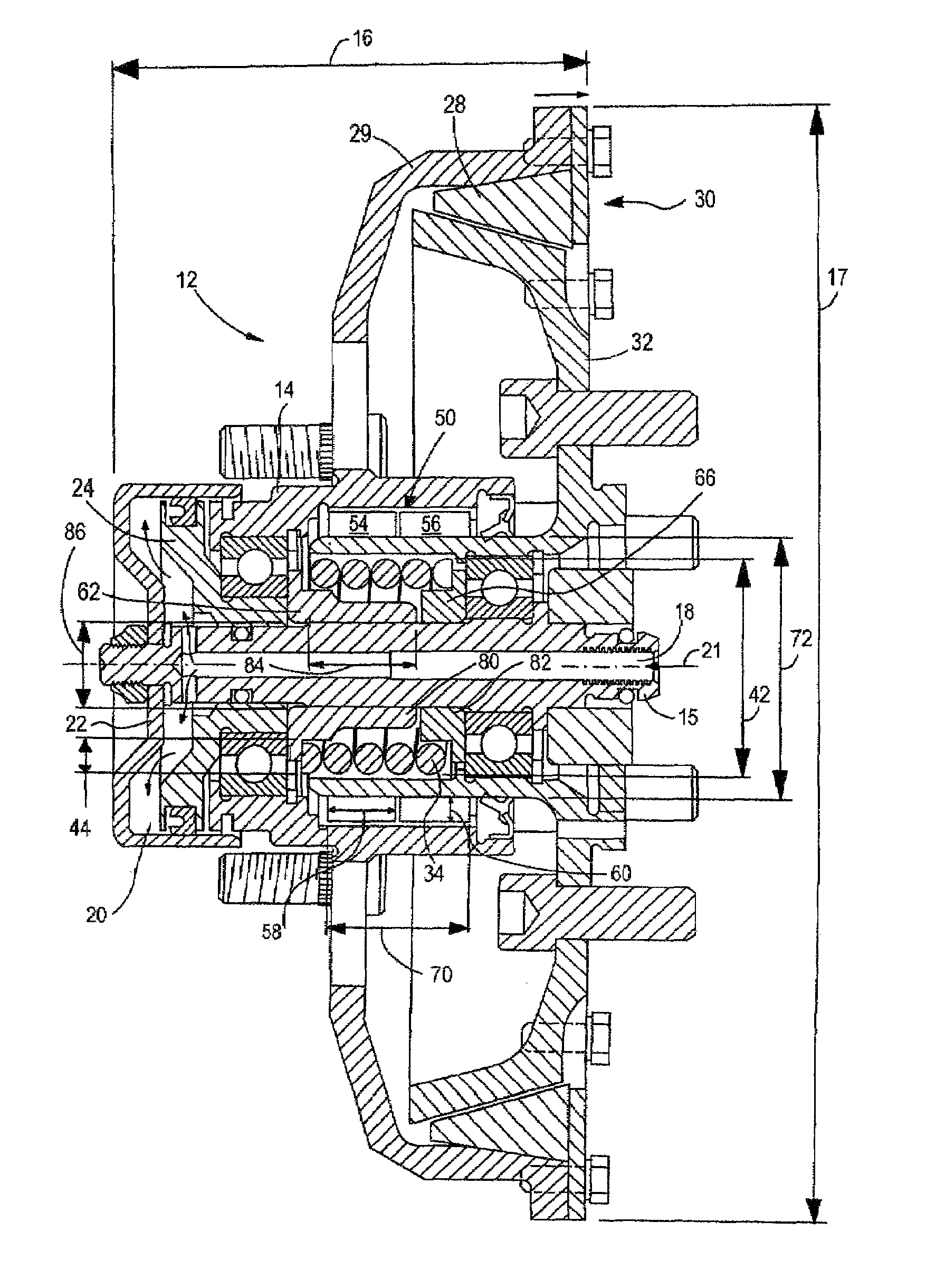
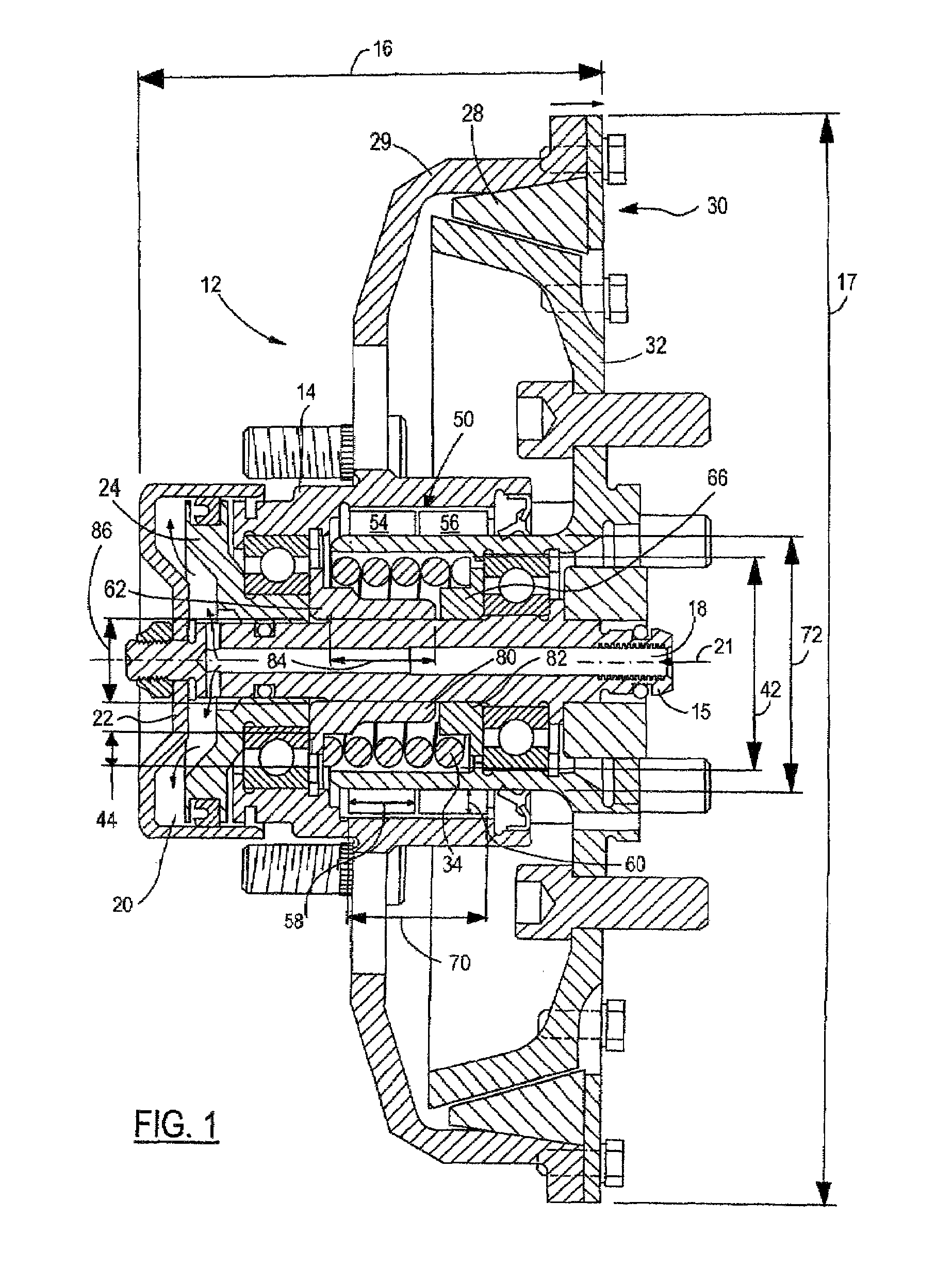
[0014]Referring now to FIG. 1 which is an airactuated cone clutch fan drive assembly 12 in accordance with the present invention. The fan drive assembly 12 has a clutch assembly length 16 and diameter 17 (housing diameter). The present invention provides novel and valuable improvements to the clutch assembly 12 that allow for the minimization of the clutch assembly length 16, which in turn allows the clutch assembly 12 to be utilized in a wide variety of automotive applications while providing minimal impact on surrounding structures. Reducing the length of the assembly results in the use of smaller and more compact components which also creates savings in material component expense. At the same time, however, it is also necessary to not reduce performance or operation of the fan clutch. Instead, it is necessary to optimize the components for accomplishing this result.

[0015]The clutch assembly 12 includes a central piston member 15 positioned within the clutch housing 14. Preferably...


PUM


Abstract

A clutch assembly having an overall diameter and overall axial length. Both the axial length and the ratio of the length to the diameter are reduced. A translatable clutch piston is in communication with a pressure chamber and is movable between a piston neutral position and a piston activated position in response to air pressure. A cone clutch member is moved from a clutch engaged position to a clutch disengaged position in response to the translatable clutch piston moving from the piston neutral position to the piston activated position. The cone clutch member engages the rotating drive shaft when in the clutch engaged position. A clutch spring member biases the cone clutch member into the clutch engaged position with a clutch engagement force. The clutch spring has a primary spring ratio of a wire diameter to a spring diameter optimized such that a maximum spring force is achieved while minimizing the spring length. A movable carrier member for the spring member has an increased axial length to reduce and limit abrasion damage to the piston and member. The bearing assembly has a reduced axial length limited by the ratio of its length to its inner diameter.

Description

CROSS-REFERENCE TO RELATED APPLICATIONS[0001]This is a continuation-in-part of U.S. patent application Ser. No. 10 / 905,505, filed on Jan. 7, 2005, now abandonedTECHNICAL FIELD[0002]The present invention relates generally to fan clutch assemblies and more particularly to methods and systems for improving and optimizing the operation and performance of airactuated cone clutch fan assemblies.BACKGROUND OF THE INVENTION[0003]Vehicle engines commonly utilize cooling assemblies to remove excess heat from the engine and maintain an optimal operating temperature. The cooling assembly pumps a coolant through the engine and other components in order to control engine temperature. Heat generated within the engine and other components is absorbed by the coolant and dispersed into the surrounding atmosphere through the use of a radiator. In order to improve dispersal by the radiator, it is common to utilize fan assemblies to draw or force air past the radiator to assist in temperature transmissi...

Claims


Application Information

Patent Timeline
Patent Type & Authority Patents(United States)
IPC IPC(8): F16D25/0632F16D13/26
CPCF16D25/082F16D25/0632
Inventor SETTINERI, SAMUEL E.
Owner BORGWARNER INC
Why Eureka
Try Eureka