
Ultrasonic surgical system

a surgical system and ultrasonic technology, applied in the field of ultrasonic surgical systems, can solve the problems of user inability to handle the switching device, waste of both money and space, and time-consuming, and achieve the effect of improving the maneuverability of the handpiece and operator convenien

Inactive Publication Date: 2010-06-08
OLYMPUS CORP
View PDF12 Cites 30 Cited by
  • Summary
  • Abstract
  • Description
  • Claims
  • Application Information

AI Technical Summary

Benefits of technology

The present invention provides an ultrasonic surgical system with improved maneuverability and operator convenience. The system offers the ability to activate or inactivate handpieces using a hand switch or foot switch, and can be retrofitted into existing surgical facilities without the need for a separate main unit. The system includes a main unit with a driving signal generator, output unit, manipulation signal sensing unit, control unit, and manipulation signal input unit. The system also includes an extension unit with an input unit for inputting a driving signal and an output unit for outputting the driving signal. The system also includes a perfusing means, sucking means, and communicating and controlling means to allow for synchronous activation of the perfusing means and sucking means when a n ultrasonic suction handpiece is selected. Overall, the ultrasonic surgical system provides improved maneuverability, operator convenience, and a more efficient and flexible approach to surgery.

Problems solved by technology

However, for complex surgery, various types of foot switch operated equipment are used, and many foot switches may be present in the operating room.
An operator must therefore be careful as not to press an incorrect foot switch, which is a source of distraction.
This, too, can be a nuisance, and also time consuming, which might be critical in the case of emergency medical services.
This is wasteful of both money and space.
However, the main unit is often located in a non-sterile area, so the user cannot handle the switching device.
The operator must therefore ask a nurse or the like to do so, and it becomes a nuisance to have to switch the handpieces.

Method used


Image

  • Ultrasonic surgical system
  • Ultrasonic surgical system
  • Ultrasonic surgical system

Examples


first embodiment

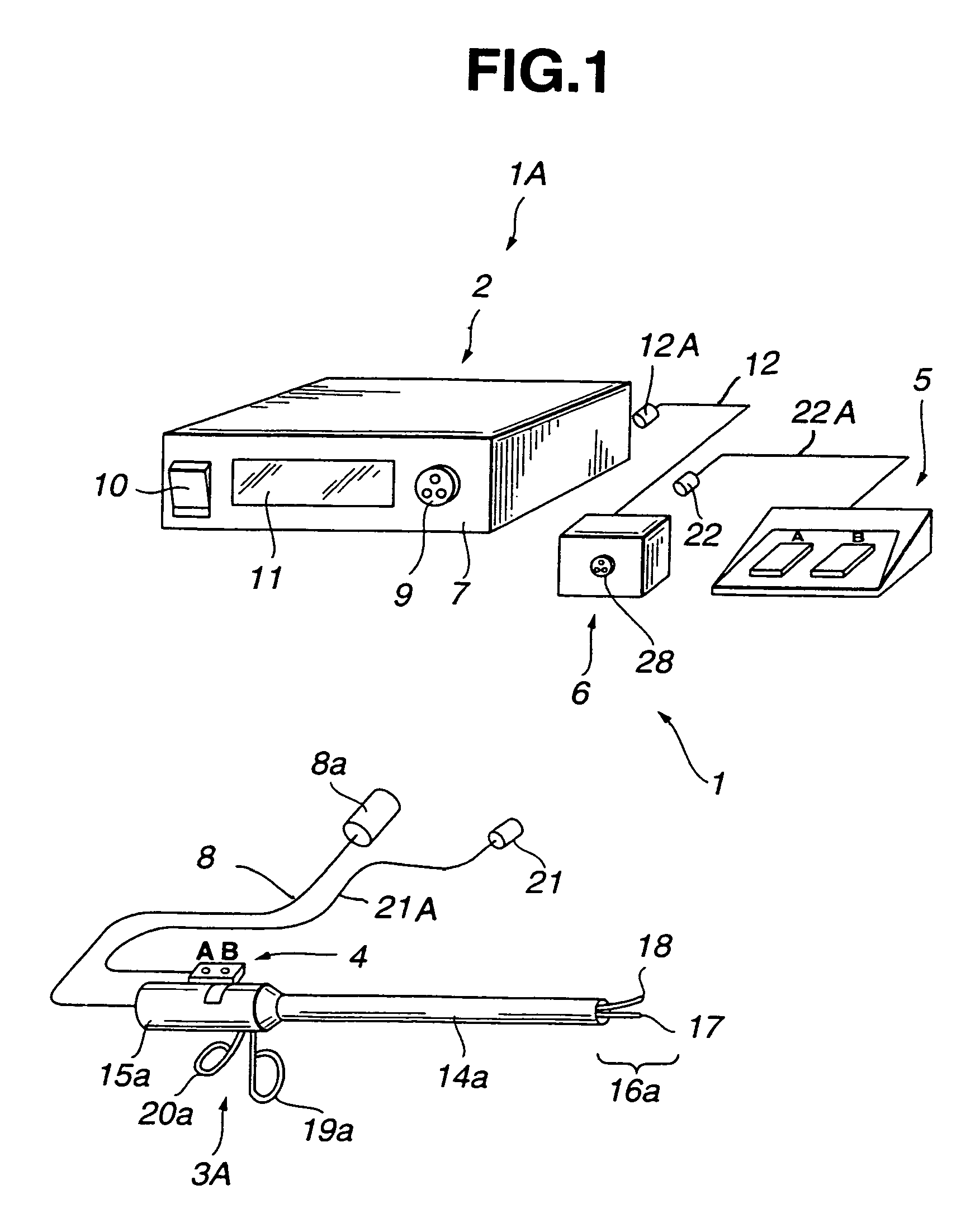
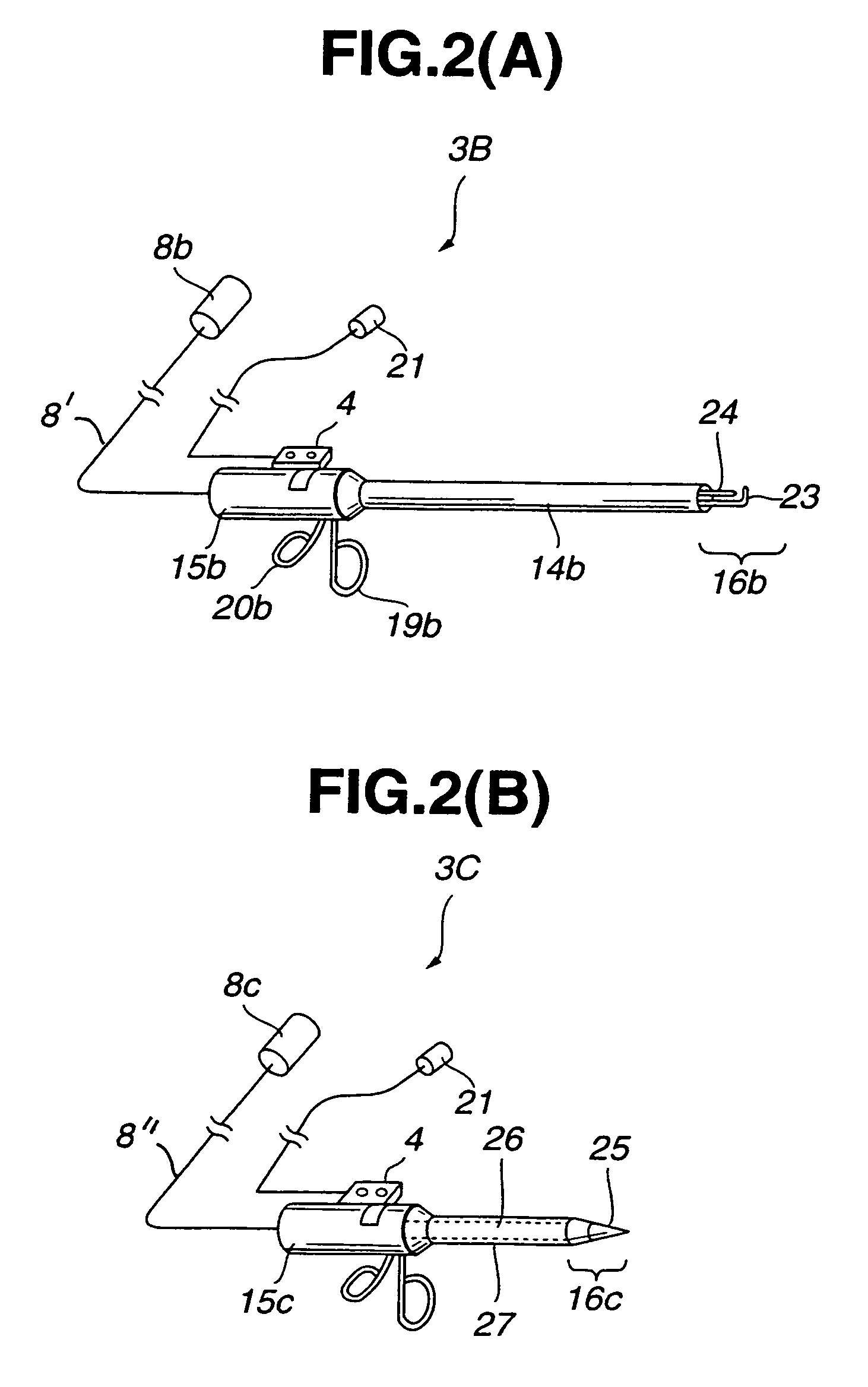
[0041]FIG. 1 to FIG. 4 relate to the present invention. FIG. 1 is an explanatory diagram schematically showing the configuration of an ultrasonic surgical system having a scissors-like handpiece” which is a first handpiece, connected to a main unit so that the handpiece can be unconnected freely. FIG. 2A and FIG. 2B are explanatory diagrams showing second and third handpieces connected to the main unit as alternatives to the scissors-like handpiece shown in FIG. 1. FIG. 2A shows the appearance of a hook-like handpiece, while FIG. 2B shows a trocar and cannula-like handpiece that is the third handpiece. FIG. 3 is a circuit block diagram showing circuits incorporated in the hand switch, a foot switch, an extension unit, and the main unit which are shown in FIG. 1. FIG. 4 is a circuit block diagram for explaining examples of circuits different from those shown in FIG. 3.

[0042]An ultrasonic surgical system 1 of the present embodiment has, as an ultrasonic surgical apparatus 1A, a main u...

second embodiment

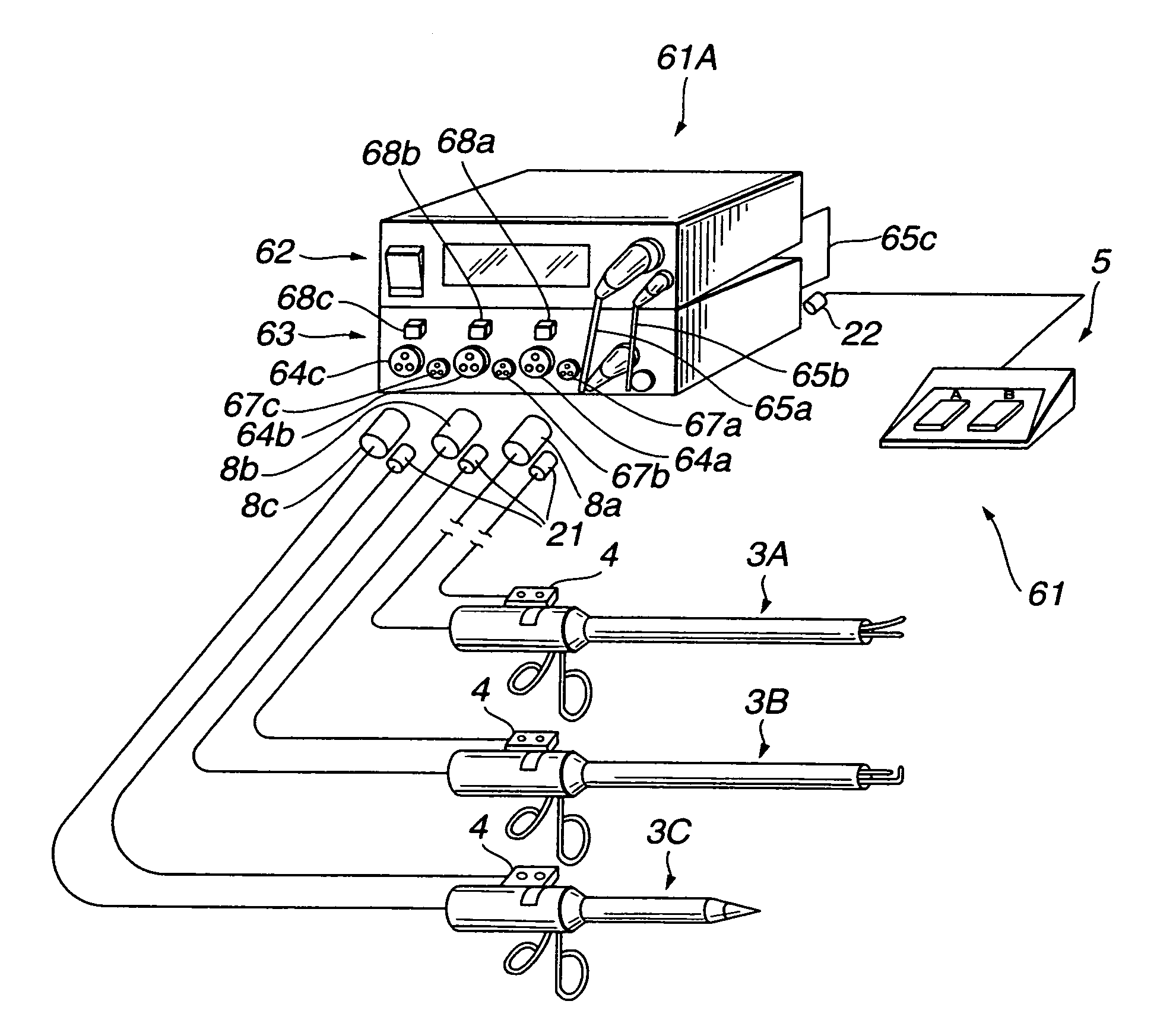
[0081]FIG. 5 and FIG. 6 relate to the present invention. FIG. 5 is an explanatory diagram schematically showing the configuration of an ultrasonic surgical system. The ultrasonic surgical system uses an ultrasonic surgical apparatus having a scissors-like handpiece, a hook-like handpiece, and a trocar and cannula-like handpiece, which are the first, second, and third handpieces, selectively connected to an extension unit so that they can be unconnected freely. FIG. 6 is a circuit block diagram of the ultrasonic surgical apparatus shown in FIG. 5.

[0082]In the first embodiment, one of the handpieces 3A, 3B, and 3C is connected to the main unit 2 at a time. In the embodiment of FIGS. 5 and 6, all three handpieces and the associated hand switches 4 may be connected to the main unit 2 at the same time. In this embodiment, the hand switches 4 are used selectively to operate the handpieces connected to the main unit 2 for different purposes.

[0083]In the circuit block diagram of the ultraso...

third embodiment

[0096]FIG. 7 to FIG. 9 relate to the FIG. 7 is an explanatory diagram schematically showing the configuration of an ultrasonic surgical system based on an ultrasonic surgical apparatus having a scissors-like handpiece, a trocar and cannula-like handpiece, and a perfusion / suction handpiece releasably connected to a connector extension unit. FIG. 8 is a circuit block diagram of the ultrasonic surgical apparatus shown in FIG. 7. FIG. 9 is a circuit block diagram of a modification of a perfusion suction unit shown in FIG. 8.

[0097]In the second embodiment, the selection switches 68a, 68b, and 68c of the connector extension unit 63 serve as selecting means, the foot switch 5, and the hand switches 4 are used selectively in order to utilize the plurality of handpieces for different purposes. Set values for the respective handpieces are manually input at the main unit 62. The set values, that is, an ultrasonic frequency or a power level are different from handpiece to handpiece. Consequent...


PUM


Abstract

An ultrasonic surgical system enables connection of a hand switch as well as a foot switch, which is used to operate a driving signal generator, without the necessity of retrofitting a main unit including the driving signal generator used to drive an ultrasonic transducer incorporated in a connected handpiece. An extension unit is included for connecting the foot switch and hand switch to the main unit. The foot switch and hand switch are connected to the main unit via the extension unit.

Description

CROSS-REFERENCE TO RELATED APPLICATIONS[0001]The present application is a divisional under 37 C.F.R. §1.53(b) of prior application Ser. No. 09 / 482,791 filed Jan. 13, 2000 now abandoned by Tomohisa SAKURAI entitled ULTRASONIC SURGICAL SYSTEM.BACKGROUND OF THE INVENTION[0002]1. Field of the Invention[0003]The present invention relates to an ultrasonic surgical system for treating a living tissue using ultrasonic waves generated by an ultrasonic transducer incorporated in a handpiece.[0004]2. Description of the Related Art[0005]Surgical apparatus utilizing ultrasonic waves have replaced electric cauterizing devices in various applications. For example, an ultrasonic knife unit and an ultrasonic trocar-and-cannula unit are described in Japanese Unexamined Patent Publication No. 9-38098, and are widely known.[0006]This sort of ultrasonic surgical apparatus has a handpiece, in which an ultrasonic transducer is incorporated, connected to a main unit which includes a driving signal generato...

Claims


Application Information

Patent Timeline
Patent Type & Authority Patents(United States)
IPC IPC(8): A61B17/20A61B17/00A61B17/32A61M1/00
CPCA61B17/320068A61B2017/00017A61B2017/00199A61B2017/00482A61M1/0058A61B2217/005A61B2217/007A61M1/0031A61B2017/00973A61B2017/320069A61B2017/320071A61B2017/32007A61B2017/320082A61M1/74A61M1/77
Inventor SAKURAI, TOMOHISA
Owner OLYMPUS CORP
Learn More