Wavefront coding interference contrast imaging systems

a contrast imaging and wavefront coding technology, applied in the direction of direction/deviation determining electromagnetic systems, optical radiation measurement, instruments, etc., can solve the problems of difficult image, difficult image, and difficult image of objects that are transparent or reflective but have variations in index of refraction or thickness, etc., to improve contrast imaging of phase objects, improve contrast imaging, and control focus-related aberration

Inactive Publication Date: 2010-06-08
UNIV OF COLORADO THE REGENTS OF
View PDF131 Cites 6 Cited by
  • Summary
  • Abstract
  • Description
  • Claims
  • Application Information

AI Technical Summary

Benefits of technology

[0027]An object of the present invention is to improve Contrast Imaging of Phase Objects by increasing depth of field and controlling focus-related aberrations. This is accomplished by using Contrast Imaging apparatus and methods with Wavefront Coding aspheric optics and post processing to increase depth of field and reduce misfocus effects. The general Interference Contrast imaging system is modified with a special purpose optical element and image processing of the detected image to form the final image. Unlike the conventional Interference Contrast imaging system, the final Wavefront Coding Interference Contrast image is not directly available at the image plane. Post processing of the detected image is required. The Wavefront Coding optical element can be fabricated as a separate component, can be constructed as an integral component of the imaging objective, tube lens, beam splitter, polarizer or any combination of such.

Problems solved by technology

Objects that are transparent or reflective but have variations in index of refraction or thickness can be very difficult to image.
A Phase Object is defined here as an object that is transparent or reflective but has variations in thickness and / or index of refraction, and thus can be difficult to image because the majority of the image contrast typically is derived from variations in the reflectance or absorption of the object.

Method used


Image

  • Wavefront coding interference contrast imaging systems
  • Wavefront coding interference contrast imaging systems
  • Wavefront coding interference contrast imaging systems

Examples


Embodiment Construction

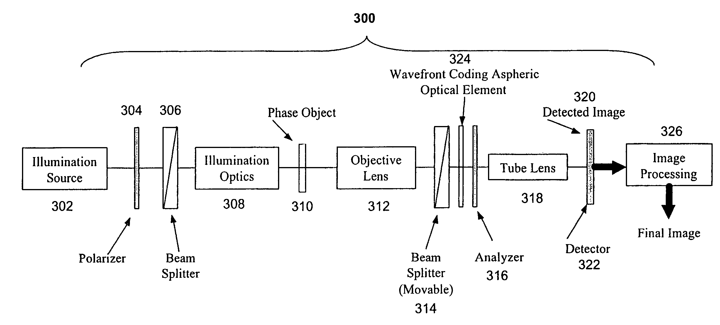
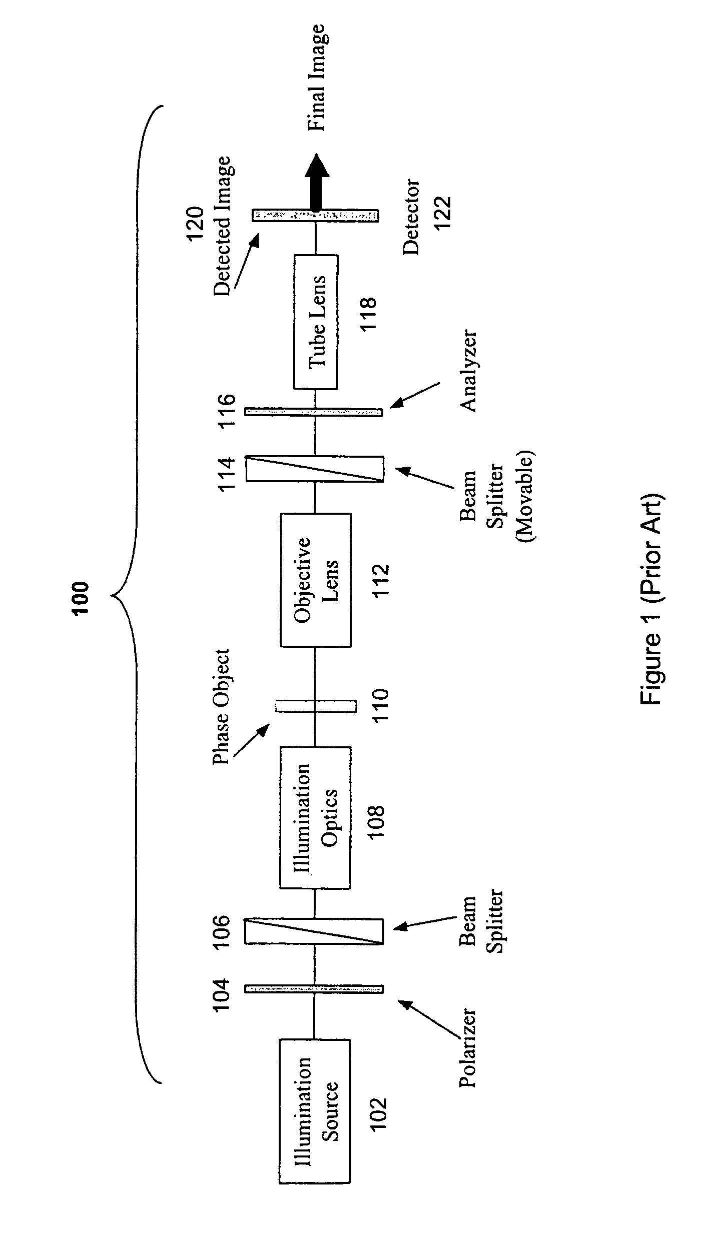
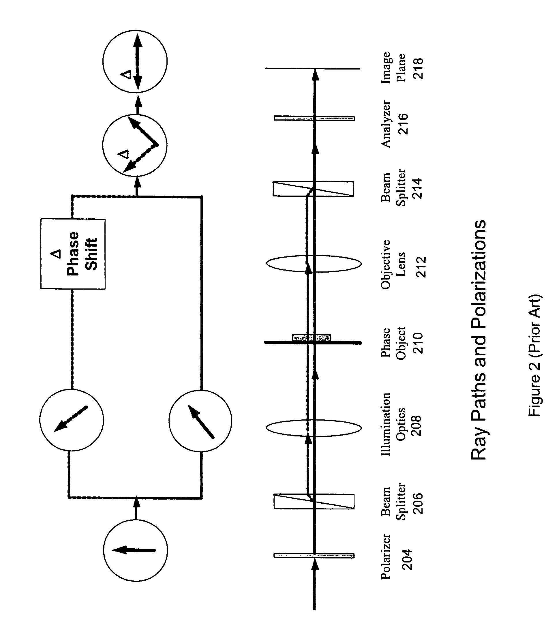
[0053]Wavefront Coding can be used with conventional objectives, polarizers and beam splitters in Interference Contrast systems, as shown in FIG. 3, to achieve an increased depth of field in an optical and digital imaging system. This can be explained by considering the Object Modifying Functions of conventional Interference Contrast systems separately from the Object Imaging Functions, as shown in FIG. 4. By considering these two functions separately, modification of depth of field can be explained in terms of the Object Imaging Function. Extending the depth of field of the Object Imaging Functions of Interference Contrast systems is shown in FIGS. 5-8. FIG. 9 shows real-world images of human cervical cells taken with a system having only Interference Contrast and a comparison to an image from a Wavefront Coding Interference Contrast system.

[0054]FIG. 3 shows a Wavefront Coded Interference Contrast imaging system 300 including Wavefront Coding and post processing in accordance with...


PUM


Abstract

An interference contrast imaging system images phase objects. The system includes an illumination source, illumination optics, polarizing optics for splitting the illumination into orthogonal polarizations and for recombining the polarizations, objective optics that form an image at a detector, a wavefront coding element and a post processor for processing the image by removing a phase shift imparted by the wavefront coding element. The wavefront coding element has an aperture, is between the phase object and the detector, and provides an altered optical transfer function of the imaging system by imparting the phase shift to the illumination transmitted through the wavefront coding element. The altered optical transfer function is insensitive to an object distance between the phase object and the objective optics over a greater range of object distances than would be provided by an optical transfer function of a corresponding interference contrast imaging system without the wavefront coding element.

Description

CROSS-REFERENCE TO RELATED APPLICATIONS[0001]This patent application is a continuation of commonly-owned and U.S. patent application Ser. No. 10 / 355,761, filed on Jan. 31, 2003, now U.S. Pat. No. 7,115,849 which is a continuation of U.S. patent application Ser. No. 09 / 875,766, filed on Jun. 6, 2001, now abandoned, both of which applications are incorporated herein by reference.[0002]This patent application is also a continuation-in-part of commonly-owned and U.S. patent application Ser. No. 09 / 070,969, filed on May 1, 1998 now U.S. Pat. No. 7,218,448; which is a continuation-in-part of U.S. patent application Ser. No. 08 / 823,894 filed Mar. 17, 1997, now U.S. Pat. No. 5,748,371; which is a continuation of U.S. patent application Ser. No. 08 / 384,257, filed Feb. 3, 1995, now abandoned, all of which are incorporated herein by reference.[0003]This patent application also relates to commonly-owned and U.S. patent application Ser. No. 09 / 766,325, filed Jan. 19, 2001, now U.S. Pat. No. 6,78...

Claims


Application Information

Patent Timeline
Patent Type & Authority Patents(United States)
IPC IPC(8): H01J3/14G01B9/02G01J1/20G02B5/18G01J9/02G01S3/783G02B5/00G02B27/00G02B27/46G02B27/52
CPCG01S3/7835G02B27/52G02B27/0025G02B27/46G02B5/00G01J9/0215
Inventor DOWSKI, JR., EDWARD RAYMONDCOGSWELL, CAROL JEAN
Owner UNIV OF COLORADO THE REGENTS OF
Why Eureka
Try Eureka