

Small-sized motor having ring-shaped field magnet
a small-sized, magnet-type technology, applied in the direction of generator/motor, magnetic circuit shape/form/construction, magnetic circuit rotating parts, etc., can solve the problems of inefficiency, disadvantage in production cost and quality, and difficult positioning and fixing of illustrated motors, so as to reduce the generation of cogging torque without excessively lowering the motor torque
- Summary
- Abstract
- Description
- Claims
- Application Information
AI Technical Summary
Benefits of technology
Problems solved by technology
Method used
Image

Examples
examples
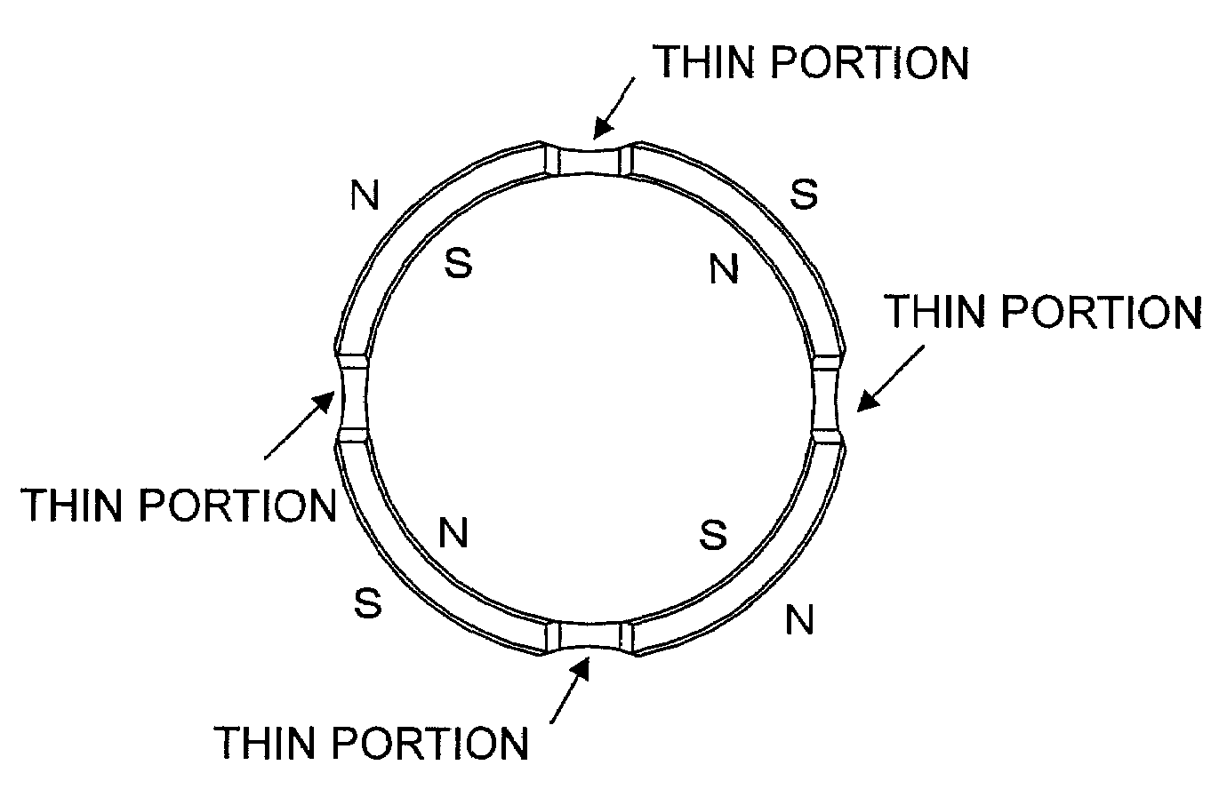
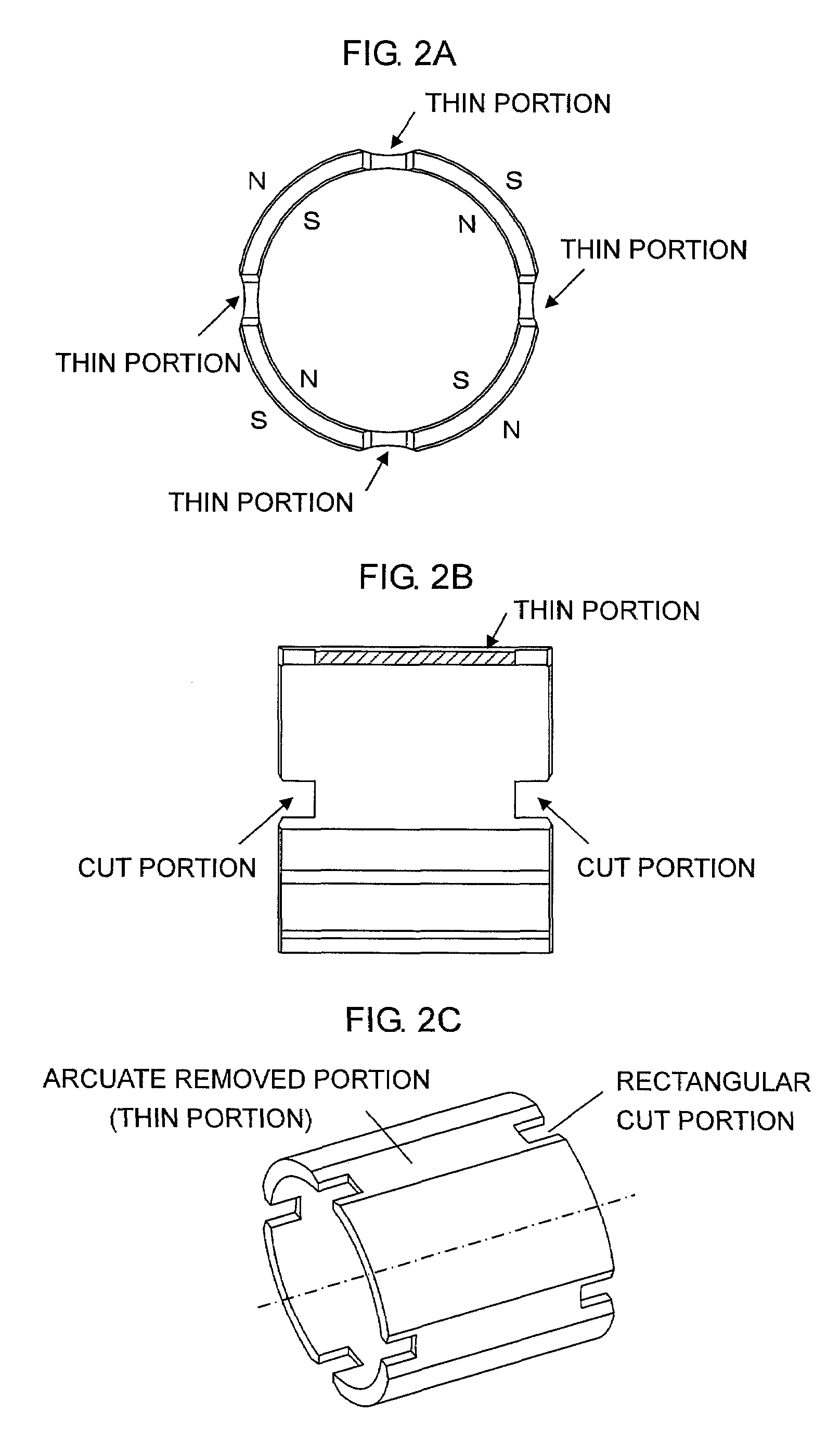
[0034]FIGS. 4A to 9B are views showing various example structures of the ring-shaped magnet. FIGS. 4A and 4B show examples structures of a magnet having four field poles in which, at each of central portions between the magnetic poles, the magnet is arcuately cut from the radially outward side to thereby form a thin portion. However, the above-described cut portions are not provided. FIG. 4A shows an example in which the four removed portions (thin portions) between the four magnetic poles have the same shape, and FIG. 4B shows an example in which the four removed portions (thin portions) have different shapes. That is, FIG. 4B shows an example in which large removed portions (arcuately removed portions) and small removed portions (arcuately removed portions) are alternately disposed in the circumferential direction.
[0035]The thin portions are not necessarily required to extend over the entire length of the magnet (in the thrust direction). As shown in FIGS. 5A and 5B, a wall portio...
PUM
 Abstract
Description
Claims
Application Information