Electrical machine comprising a winding system with coil groups

a technology of electric machines and coil groups, which is applied in the direction of windings, synchronous machines with stationary armatures, windings, etc., can solve the problems of torque ripple during operation, and achieve the effects of suppressing the influence of virtual teeth, reducing ripple, and improving torque response results

Inactive Publication Date: 2010-06-08
SIEMENS AG
View PDF9 Cites 26 Cited by
  • Summary
  • Abstract
  • Description
  • Claims
  • Application Information

AI Technical Summary

Benefits of technology

[0013]In accordance with the invention, the influence of these virtual teeth can be suppressed by reciprocal compensation of the revolving regions with local saturation. This is achieved by means of the winding system according to the invention which is particularly advantageous in this regard. The individual magnetic fields produced by the two individual coils given the pole pair number have an electrical offset angle (=phase shift) of an odd-numbered multiple of 30° and, given the sixth harmonic of the pole pair number, have an electrical offset angle of an odd-numbered multiple of 180°. The individual magnetic fields therefore cancel one another out given the sixth harmonic and therefore precisely in terms of their disadvantageous effect on the torque owing to the virtual teeth, with the result that overall a greatly improved torque response results with reduced ripple.
[0014]One variant is favorable in which the individual coils are in the form of tooth-wound coils and in particular in each case surround a tooth arranged between adjacent slots. Tooth-wound coils simplify the manufacture o

Problems solved by technology

Such an electrical machine, which is in particular in the form of a permanent magne

Method used


Image

  • Electrical machine comprising a winding system with coil groups
  • Electrical machine comprising a winding system with coil groups
  • Electrical machine comprising a winding system with coil groups

Examples


Embodiment Construction

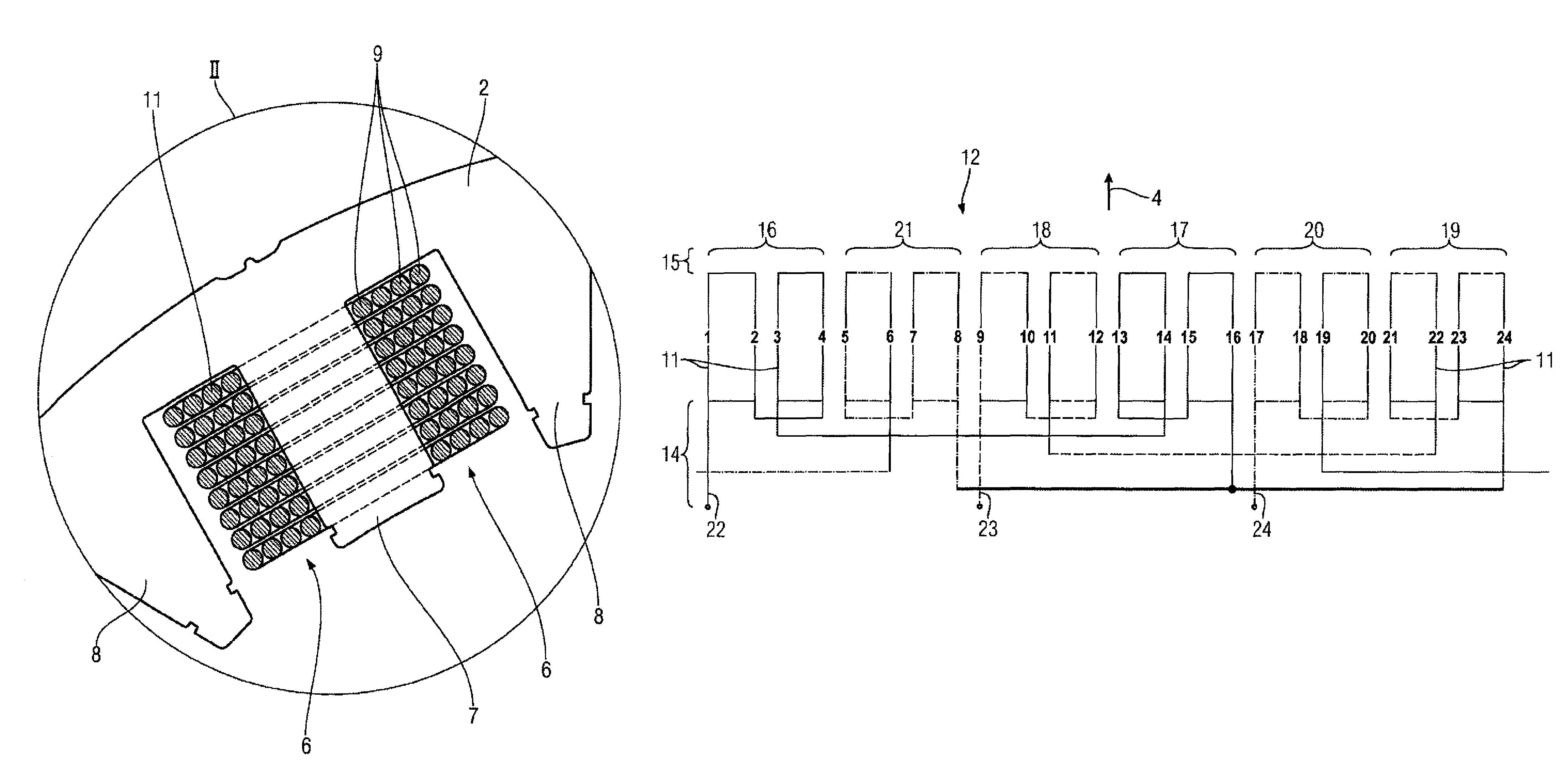
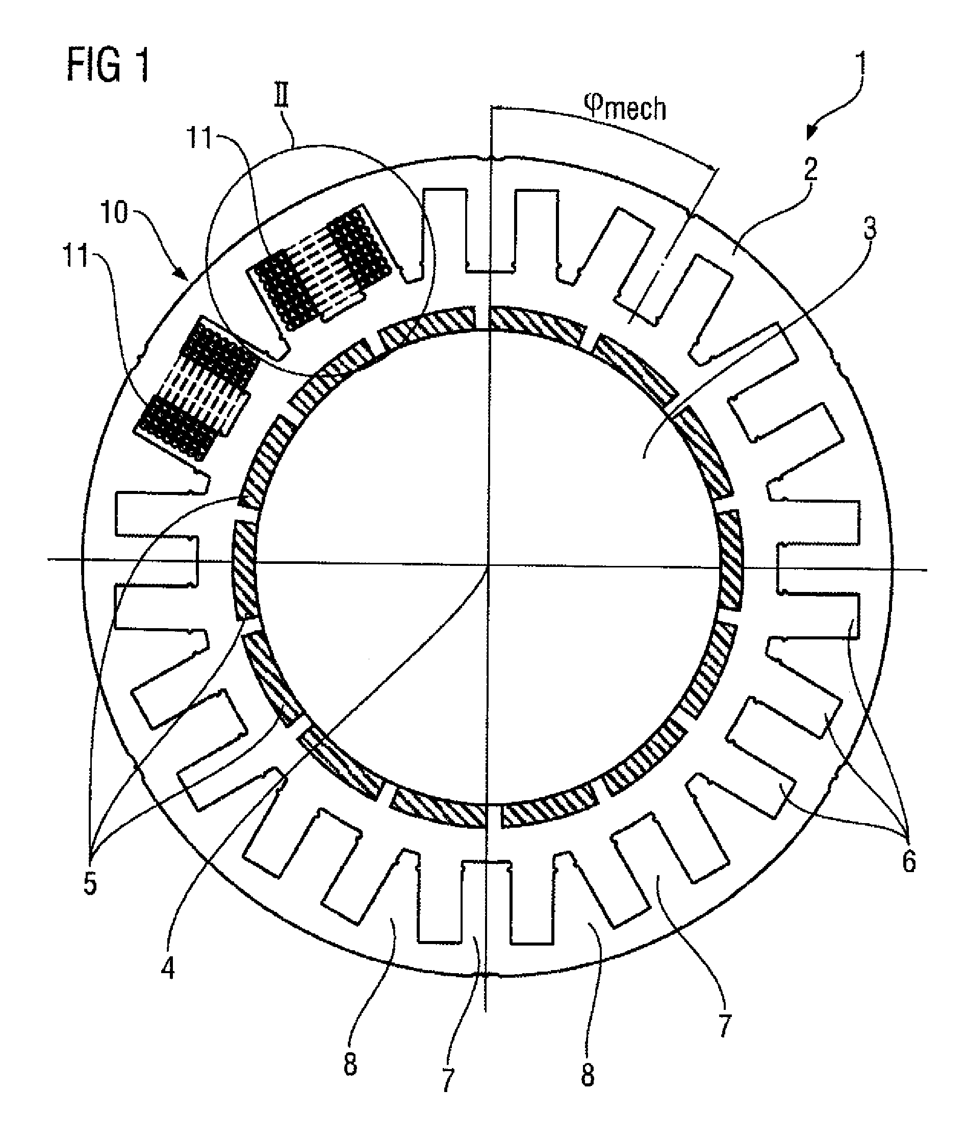
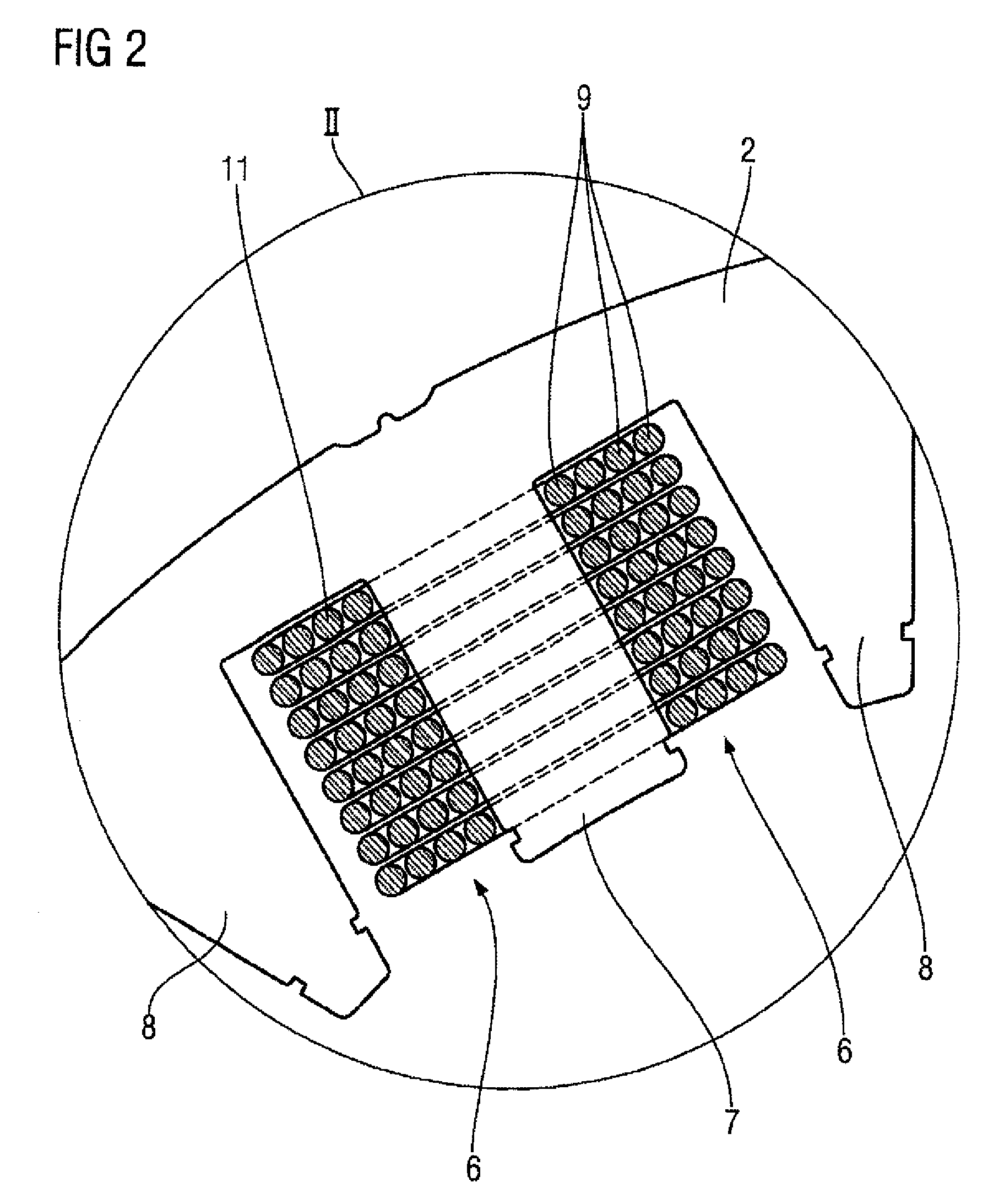
[0026]Mutually corresponding parts have been provided with the same reference symbols in FIGS. 1 to 4.

[0027]FIG. 1 shows an exemplary embodiment of an electrical machine 1 in a cross-sectional illustration. It is in the form of a permanent magnet synchronous motor and contains a stator 2 and a rotor 3, which is mounted such that it is capable of rotating about an axis of rotation 4. The rotor 3 is an internal rotor, which in the exemplary embodiment is provided with in total fourteen permanent magnets 5, which results in a pole pair number pN of seven. The stator 2 contains, on its inner wall facing the rotor 3, a plurality of, in the exemplary embodiment in FIG. 1 in total 24, slots 6 which are distributed uniformly over the circumference and between which in each case one tooth 7 with parallel flanks or one tooth 8 with non-parallel flanks is arranged. The teeth 7 and 8 alternate in the circumferential direction. They are connected to one another by an externally peripheral yoke. ...


PUM


Abstract

Disclosed is an electric machine (1) comprising a stator (2) that encompasses a winding system (10) with three winding branches, and a certain number of effective pole pairs. Each winding branch is provided with at least one coil group, each of which contains an even number of serially connected individual coils (11) that generate an individual magnetic field, respectively. Two respective individual coils (11) of a coil group are offset relative to each other in a circumferential direction of the stator (2) in such a way that the associated individual magnetic fields are provided with an offset electrical angle relative to one another at the sixth harmonic of the number of effective pole pairs, said offset electrical angle being equal to an odd multiple of 180°.

Description

BACKGROUND OF THE INVENTION[0001]The invention relates to an electrical machine with a stator, which comprises a winding system with three winding phases, and with a pole pair number.[0002]Such an electrical machine, which is in particular in the form of a permanent magnet synchronous machine, often has a certain degree of torque ripple during operation. In order to reduce this torque ripple, various measures are known.[0003]DE 199 61 760 A1 has disclosed that special winding factors of the winding system arranged in slots of the stator and skewing of the slots result in a reduction in the torque ripple.[0004]Furthermore, DE 101 14 014 A1 has disclosed a permanent magnet polyphase machine, whose stator has skewed slots for accommodating the winding system. The special embodiment of the stator and the winding system results in extensive suppression of the cogging and the fifth harmonic.[0005]Despite these known measures, there is a need to further reduce the torque ripple. This is pa...

Claims


Application Information

Patent Timeline
IPC IPC(8): H02K3/28H02K1/16
CPCH02K21/16H02K3/28
Inventor VOLLMER, ROLFSCHUNK, HOLGERSTORATH, ALBRECHT
Owner SIEMENS AG
Why Eureka
Try Eureka