Supercharge Your Innovation With Domain-Expert AI Agents!

Image display apparatus, three-dimensional image display apparatus, and three-dimensional image display system

a display apparatus and image technology, applied in the field of image display apparatus, can solve the problems of inability to display images with high precision, large quantization error in images to be displayed, and limited image display accuracy of conventional image display apparatus

Inactive Publication Date: 2010-06-08
NTT DOCOMO INC
View PDF10 Cites 3 Cited by
  • Summary
  • Abstract
  • Description
  • Claims
  • Application Information

AI Technical Summary

Benefits of technology

The present invention provides an image display apparatus, a three-dimensional image display system, and a method for forming electric field displacement surfaces with an image pattern. These improvements eliminate limitations caused by the size and shape of each pixel electrode and crosstalk, resulting in improved image display precision. The invention includes a light modulation device with an electro-optic effect, a plurality of control points, and an electric field control section to form electric field displacement surfaces with an image pattern. The electric field control section can synthesize pre-change and post-change electric field displacement surfaces to create surfaces with the desired image pattern. The invention can be used in a three-dimensional image display system by providing a server device with an interference fringe computing section, a storage section, and a transmission section to transmit the necessary voltage values to the light modulation device.

Problems solved by technology

Thus, there is a problem in that the precision of images which can be displayed by the conventional image display apparatus is limited by the size and shape of each pixel electrode 23a.
In other words, the conventional image display apparatus has a problem in that since the miniaturization of the pixel electrodes 23a is limited, a quantization error in an image to be displayed becomes large, making it impossible to display the image with high precision.
Further, the conventional image display apparatuses have a problem in that crosstalk caused by voltages to be applied to pixel electrodes 23a is generated between adjacent pixels (rectangular regions).

Method used


Image

  • Image display apparatus, three-dimensional image display apparatus, and three-dimensional image display system
  • Image display apparatus, three-dimensional image display apparatus, and three-dimensional image display system
  • Image display apparatus, three-dimensional image display apparatus, and three-dimensional image display system

Examples


first embodiment

Configuration of a Three-Dimensional Image Display System According to the Present Invention

[0073]FIG. 4 is a diagram showing the entire configuration of a three-dimensional image display system according to a first embodiment of the present invention.

[0074]The three-dimensional image display system according to this embodiment displays a three-dimensional image by using a calculated interference fringe (computer generated hologram) as a display-target image.

[0075]In this embodiment, there is an idea that a term “image” includes both a still image and a moving image (picture or video).

[0076]As shown in FIG. 4, the three-dimensional image display system according to this embodiment is provided with an interference fringe computing apparatus 1, a three-dimensional image display apparatus 2, and a reference beam irradiation apparatus 3.

[0077]The interference fringe computing apparatus 1 is configured by a computer, and is configured to calculate an interference fringe generated by a re...

second embodiment

(Configuration of a Three-Dimensional Image Display System According to the Present Invention)

[0122]FIG. 11 is a diagram showing the entire configuration of a three-dimensional image display system according to a second embodiment of the present invention. The three-dimensional image display system according to this embodiment will be described with reference to FIGS. 11 to 16.

[0123]Note that as for the configuration of the three-dimensional image display system according to this embodiment, differences from the configuration of the three-dimensional image display system according to the above-described first embodiment will be mainly described.

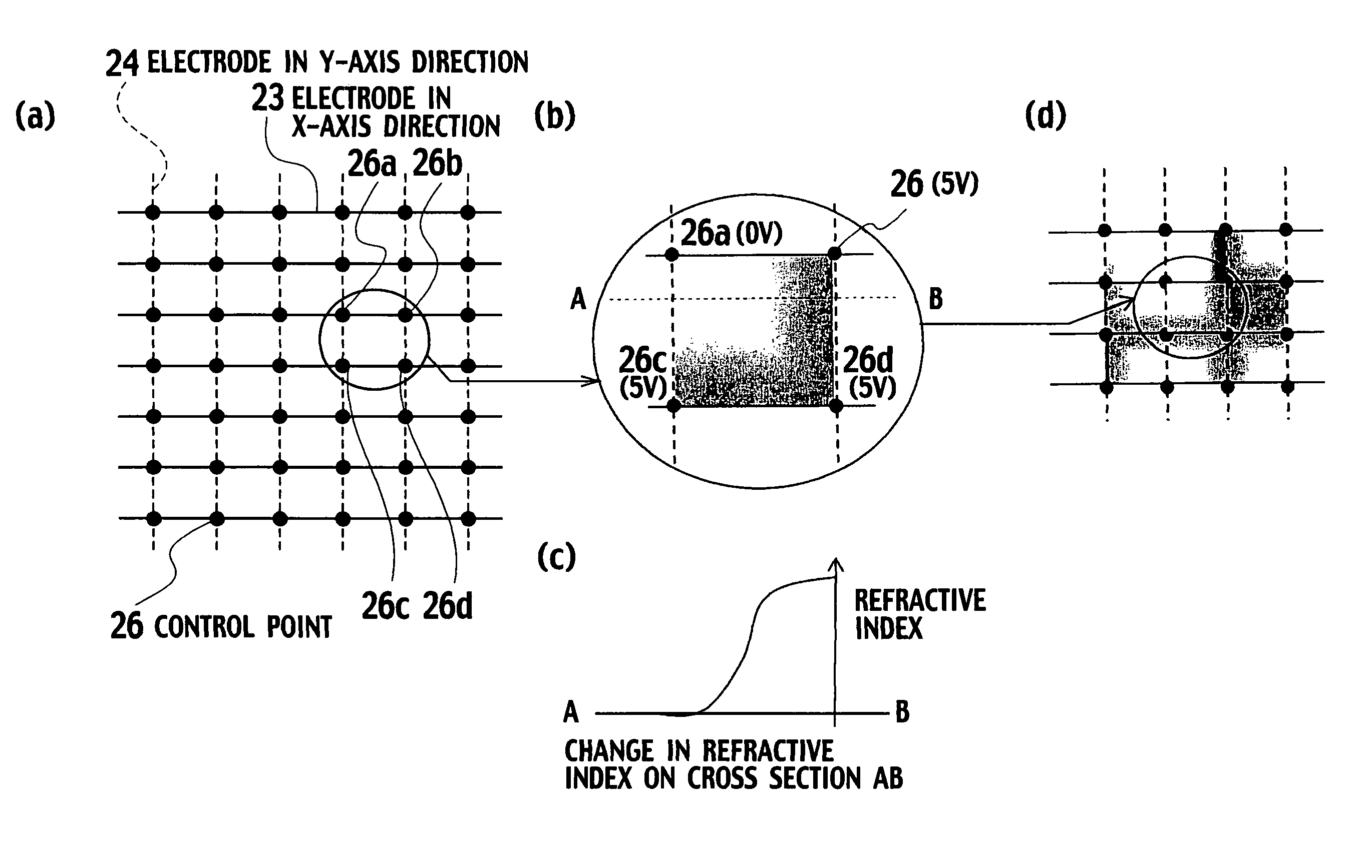
[0124]As shown in FIG. 11, a three-dimensional image display apparatus 2 according to this embodiment is provided with an electrode moving section 27 in addition to the configuration of the three-dimensional image display apparatus 2 according to the above-described first embodiment.

[0125]Each of the plural control points 26 is configured in ...

third embodiment

(A Three-Dimensional Image Display System According to the Present Invention)

[0178]A three-dimensional image display system according to a third embodiment of the present invention will be described with reference to FIGS. 18 and 19.

[0179]As shown in FIG. 18, the three-dimensional image display system according to this embodiment is provided with a light modulation device moving section 27a in place of the electrode moving section 27 described in the second embodiment.

[0180]The other configurations are the same as those of the three-dimensional image display system of the above-described second embodiment.

[0181]In this embodiment, the relative positional relationship between a light modulation device 25 and each of plural control points 26 is configured to be able to be changed. The light modulation device 25 is configured to be able to be moved by the light modulation device moving section 27a.

[0182]Specifically, as shown in FIG. 19, the light modulation device 25 is configured to...


PUM


Abstract

An image display apparatus includes: a light modulation device having an electro-optic effect in which a refractive index changes according to electric field intensity; a plurality of control points provided on a surface of the light modulation device; and an electric field control section configured to control voltage values to be applied to the plurality of control points, and to form electric field displacement surfaces having a predetermined image pattern in the light modulation device.

Description

CROSS REFERENCE TO RELATED APPLICATION[0001]This application is based upon and claims the benefit of priority from the prior Japanese Patent Application No. P2004-342965 and P2004-342983, filed on Nov. 26, 2004; the entire contents of which are incorporated herein by reference.BACKGROUND OF THE INVENTION[0002]1. Field of the Invention[0003]The present invention relates to an image display apparatus, and also to a three-dimensional image display apparatus and a three-dimensional image display system in which a calculated interference fringe (computer generated hologram) is used to display a three-dimensional image.[0004]2. Description of the Related Art[0005]Conventionally known are image display apparatuses for displaying an image which is formed in a light modulation device by applying a voltage to the light modulation device. Such image display apparatuses include a liquid crystal display (LCD), for example.[0006]Here, the light modulation device is a device having an electro-opti...

Claims


Application Information

Patent Timeline
Patent Type & Authority Patents(United States)
IPC IPC(8): G09G3/00G02B27/22G09G3/34H04N13/00G09G5/00G03H1/00G06F3/038
CPCG02F1/0316G02F1/0558G03H1/02G03H1/0841G03H1/2294G02F1/0551G03H2210/30G03H1/08G03H2001/0224G03H2001/0833G03H2225/12G03H2225/22G03H2225/32G03H2226/04G03H2227/02G03H2240/56G03H1/26
Inventor HORIKOSHI, TSUTOMUTSUBOI, MASASHI
Owner NTT DOCOMO INC
Features
  • R&D
  • Intellectual Property
  • Life Sciences
  • Materials
  • Tech Scout
  • Unparalleled Data Quality
  • Higher Quality Content
  • 60% Fewer Hallucinations
Learn More