Structural vented roof deck enclosure system

a ventilation and roof technology, applied in the field of roof systems, can solve the problems of reducing the quality of finished products, increasing construction costs, and arising from several problems in the foregoing systems, and achieve the effect of reducing both material and labor costs

Inactive Publication Date: 2010-06-15
AYERS JR W HOWARD
View PDF51 Cites 22 Cited by
  • Summary
  • Abstract
  • Description
  • Claims
  • Application Information

AI Technical Summary

Benefits of technology

[0007]The embodiments of the present invention provide structural support for metal decks and replace the wood blocking, heavy structural steel angles or bent plates used in prior art systems with a cold formed galvanized steel that is stronger and lighter, thus reducing both material and labor costs. Further, the structural support members can be used at any of the edges of the roof deck, whether terminal or otherwise (e.g. skylights).

Problems solved by technology

Several problems have arisen in the foregoing systems.
For example, the wood blocking must be custom designed on-site, resulting in a significant increase in construction expense.
The on-site nature of the design and construction of conventional systems reduces the quality of the finished product because it is not manufactured under controlled conditions.
In addition to difficulties associated with construction, conventional systems have typically not been designed to provide stable support for finished fascia material and other components of roof deck terminations.
Further, the wood blocking suffers problems inherent with such materials such as rotting, warping, burning, shrinking, and being subject to attack by termites.
The chemicals used in treating, the wood blocking to overcome its inherent problems frequently results in corrosion of the metal decks, metal fasteners, and other metal materials in contact with the treated wood.
Finally, current low-slope rooting systems do not provide exit venting for the roof deck at its perimeters.

Method used


Image

  • Structural vented roof deck enclosure system
  • Structural vented roof deck enclosure system
  • Structural vented roof deck enclosure system

Examples


second embodiment

[0023]In a second embodiment shown in FIGS. 4-6, a structural support member 30 is supported on an upper surface 11a of a roof deck support structure 11, such as bar joists, that are, in turn, supported on a wall 12. The structural support member 30, best shown in FIG. 5, comprises a substantially vertical outer segment 31 having an upper end 31a and a lower end 31b that overlaps the outer surface 11b of the support structure and is in a substantially parallel-planar relationship therewith. Because the outer segment 31 and the outer surface 11b of the support structure 11 are in parallel-planar relationship with each other and are in abutment with each other, they are substantially co-planar and are referred to herein as such. The vertical outer segment 31 may include an angled cleat 31c for securing fascia 16 thereto. The structural support member 30 further comprises a substantially horizontal lower segment 32 having a first end 32a connected to outer segment 31 and a second end 3...

third embodiment

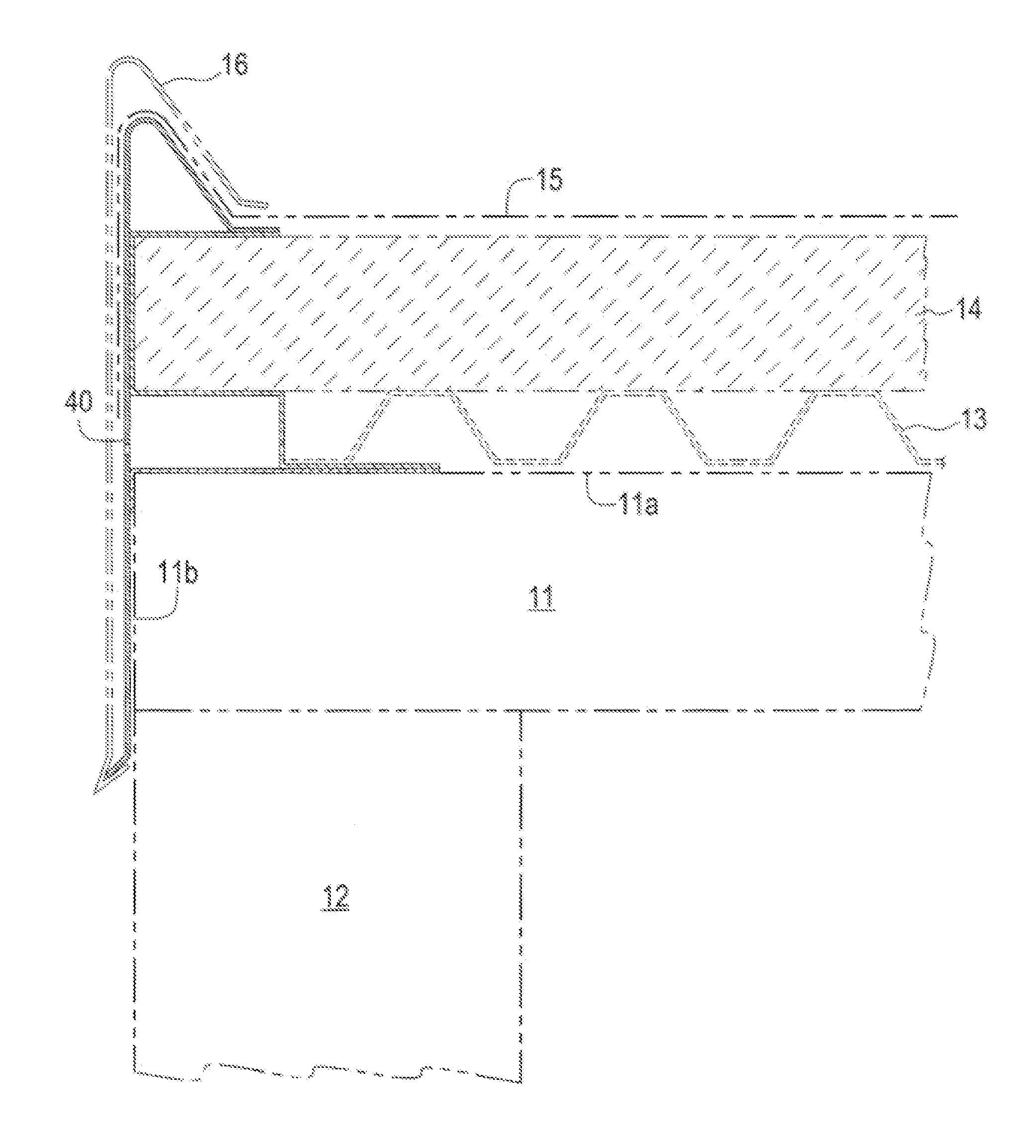
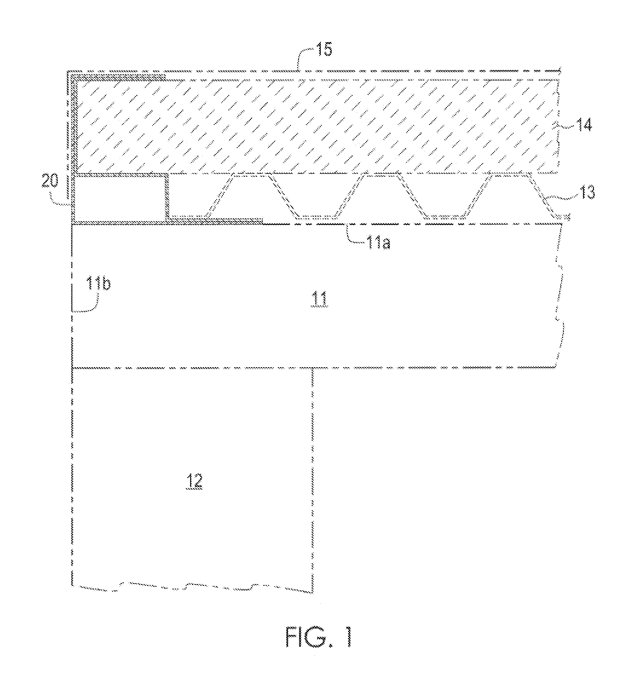
[0025]In a third embodiment shown in FIGS. 7-9, a structural support member 40 is supported on an upper surface 11a of a roof deck support structure 11, such as bar joists, that are, in turn, supported on a wall 12. The structural support member 40, best shown in FIG. 8, comprises a substantially vertical outer segment 41 having an upper end 41a and a lower end 41b that overlaps the outer surface 11b of the support structure and is substantially co-planar therewith. Because the outer segment 41 and the outer surface 11b of the support structure 11 are in parallel-planar relationship with each other and are in abutment with each other, they are substantially co-planar and are referred to herein as such. The vertical outer segment 41 may include an angled cleat 41c for securing fascia 16 thereto. The structural support member 40 further comprises a substantially horizontal lower segment 42 having a first end 42a connected to the outer segment 41 and a second end 42b, a substantially h...

fourth embodiment

[0027]In a fourth embodiment shown in FIGS. 10-12, a structural support member 60 is supported on an upper surface 11a of a roof deck support structure 11, such as bar joists, that are, in turn, supported on a wall 12. In this embodiment, the upper surface 11a of the roof deck support, structure 11 intersects an inner surface 17a of a parapet wall 17. The structural support member 60, best shown in FIG. 11, comprises a substantially vertical outer segment 61 having an upper end 61a and a lower end 61b wherein the outer segment 61 is substantially co-planar with the inner surface 17a of the parapet wall 17. Because the outer segment 61 and the inner surface 17a of the parapet wall 17 are in parallel-planar relationship with each other and are in abutment with each other, they are substantially co-planar and are referred to herein as such. The structural support member 60 further comprises a substantially horizontal lower segment 62 having a first end 62a connected to the lower end 61...


PUM


Abstract

A structural support member for use in a roof deck system that is supported on an upper surface of a roof deck support structure. The primary embodiment comprises a substantially vertical outer segment, a substantially horizontal lower segment connected to the outer segment, a substantially horizontal upper segment connected to the outer segment, a substantially horizontal intermediate segment connected to the outer segment between the upper and lower segments, and a substantially vertical inner segment connected to the intermediate segment and the lower segment. The lower segment is secured to the upper surface of the support structure and supports a metal deck. The upper, intermediate, and outer segments form a C-shaped cavity for receiving the end of a barrier material, such as insulation or concrete, which is supported on the metal deck. The lower, intermediate, inner, and outer segments form an elongated channel that preferably has a plurality of vent holes therethrough.

Description

FIELD OF THE INVENTION[0001]The present invention relates to roof systems, and more particularly, to roof deck systems having the edges of the roof decks enclosed within uniform structural supports.BACKGROUND OF THE INVENTION[0002]Commercial roof systems commonly comprise a roof deck system utilized to support a roof membrane. Some of these commercial roof systems comprise a metal deck, such as a sheet of corrugated steel, mounted on a support structure such as steel or wooden roof beams. The metal deck supports a barrier material, such as rigid insulation or lightweight concrete, which, in turn, supports the roof membrane. Along the terminal edges of the roof deck system, pressure treated wood is frequently used as blocking, wherein the wood blocking is supported on the metal deck and lies immediately adjacent to the barrier material.[0003]Several problems have arisen in the foregoing systems. For example, the wood blocking must be custom designed on-site, resulting in a significan...

Claims


Application Information

Patent Timeline
Patent Type & Authority Patents(United States)
IPC IPC(8): E04B7/00
CPCE04D13/155E04D13/15
Inventor AYERS, JR., W. HOWARD
Owner AYERS JR W HOWARD
Why Eureka
Try Eureka