Device for connecting two rotating shafts, in particular in a turbomachine

a technology of rotating shafts and connecting devices, which is applied in the direction of couplings, machines/engines, manufacturing tools, etc., can solve the problems of limiting the service life of rotating shafts, and achieve the effect of simple, effective and economi

Active Publication Date: 2010-06-15
SN DETUDE & DE CONSTR DE MOTEURS DAVIATION S N E C M A
View PDF14 Cites 23 Cited by
  • Summary
  • Abstract
  • Description
  • Claims
  • Application Information

AI Technical Summary

Benefits of technology

[0004]The object of the invention is in particular to provide a simple, effective and economic solution to this problem.
[0006]In this connection device, the greater torsional flexibility of that portion of the driven shaft which is close to one end of the splines of the driving shaft makes it possible to reduce the maximum stresses applied to this end in operation, it being possible for this reduction to be around 30% and to significantly increase the life of the driving shaft.
[0008]The driven shaft (and / or the driving shaft) thus has two splined portions separated longitudinally from one another by a torsionally more flexible portion, thus making it possible to reduce the stresses applied to the splines of one splined end portion of this shaft while increasing the stresses applied to the ends of the splines of the other splined portion of this shaft.
[0010]In one embodiment of the invention, the splined region of the driven shaft comprises at least two cylindrical portions having a greater torsional flexibility, these two cylindrical portions being separated from one another.
[0013]The torsional flexibility of the driven shaft can be increased, in the or each aforementioned cylindrical portion, by reducing its thickness and / or its diameter, and / or by machining, for example by drilling.

Problems solved by technology

In operation, the splines of the two shafts are elastically deformed in torsion, and it is found that the stresses are maximum at the longitudinal ends of the splines of the male shaft, which is the turbine shaft, this concentration of stresses limiting the service life of this shaft.

Method used


Image

  • Device for connecting two rotating shafts, in particular in a turbomachine
  • Device for connecting two rotating shafts, in particular in a turbomachine
  • Device for connecting two rotating shafts, in particular in a turbomachine

Examples


Embodiment Construction

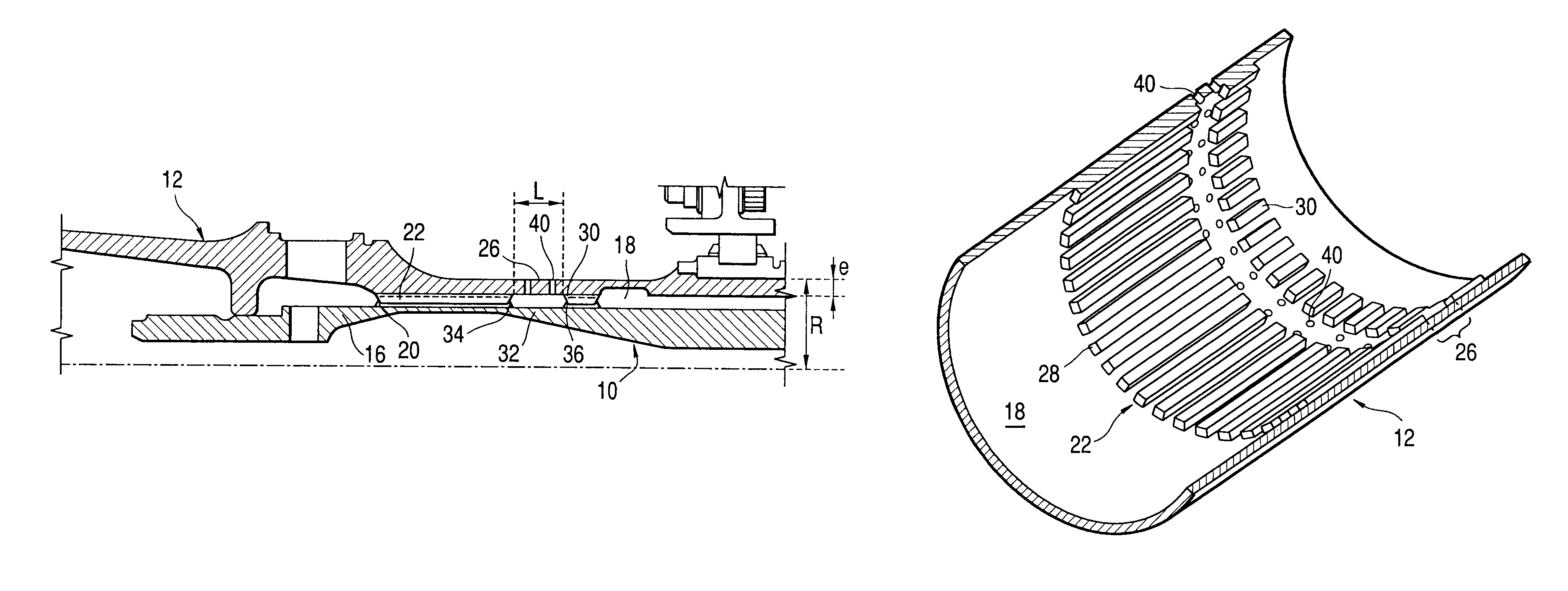
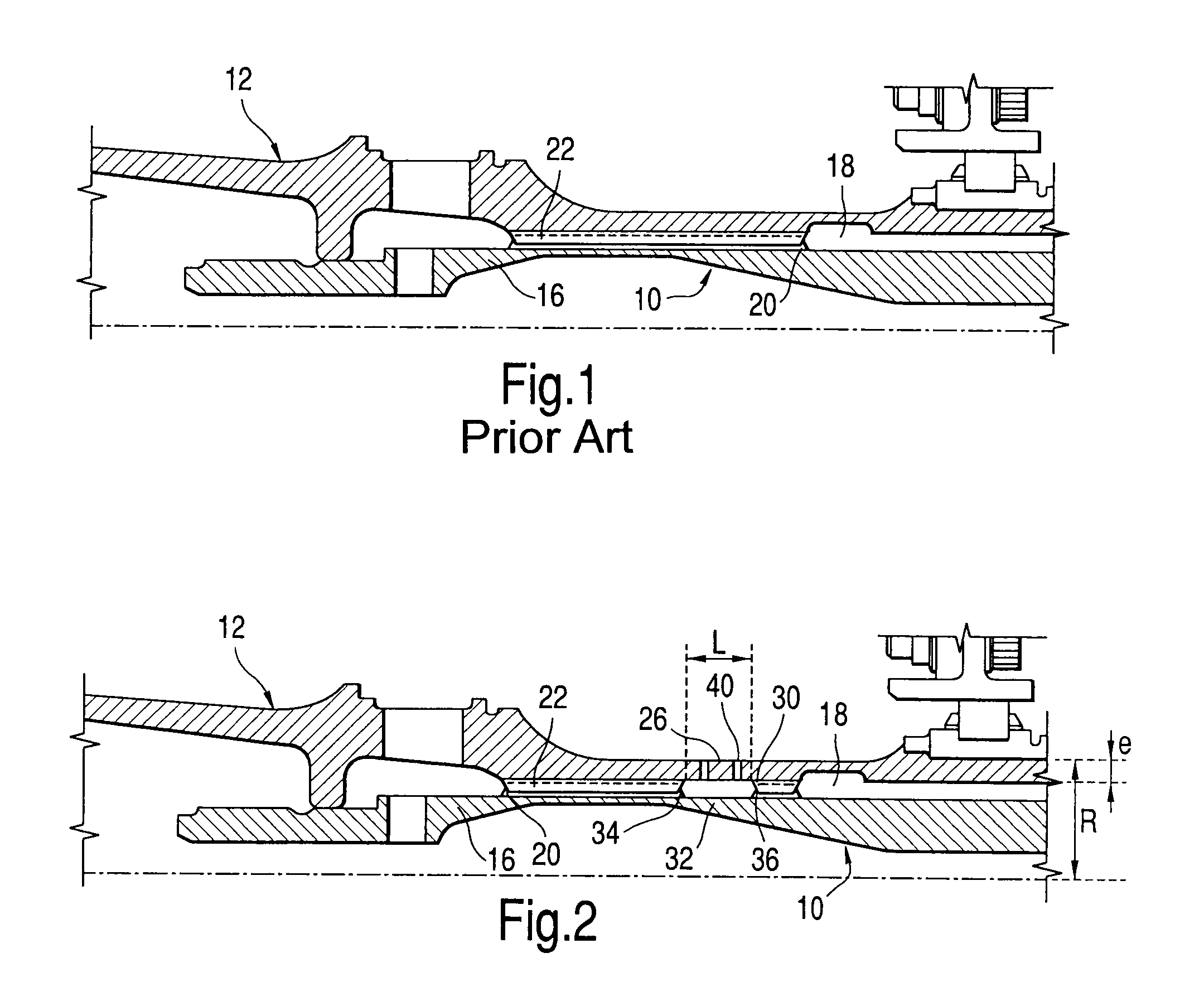
[0022]FIG. 1 is a highly schematic representation of a shaft 10 of a low-pressure turbine and a shaft 12 of a low-pressure compressor of a turbomachine such as an aircraft turbofan or turboprop, the turbine shaft 10 driving the shaft 12 of the compressor about the longitudinal axis 14 of the turbomachine by means of a prior art connection device which uses splines to produce the connection.

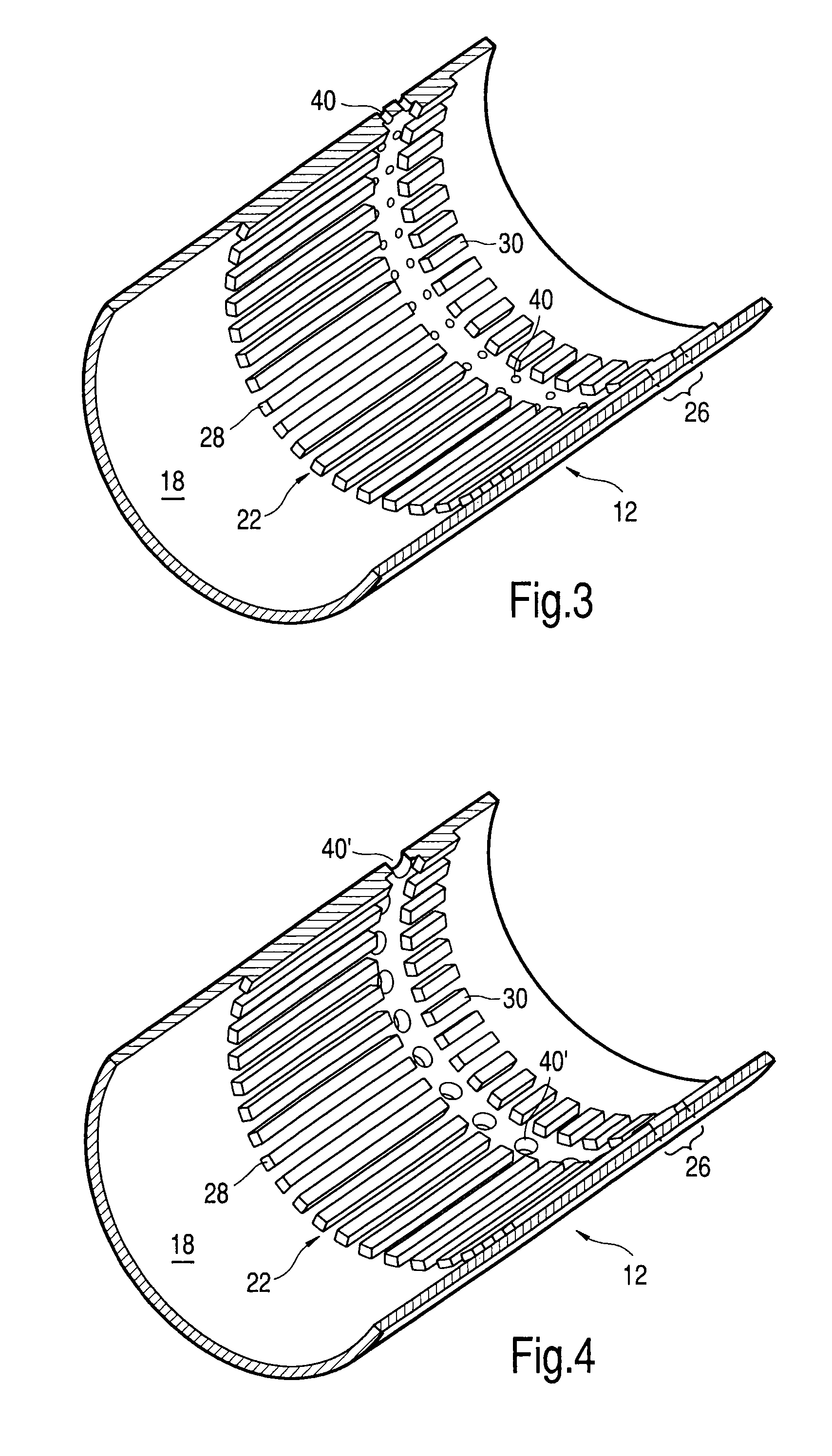
[0023]The upstream end 16 of the turbine shaft 10 forms a male cylindrical portion which is engaged in a female cylindrical passage 18 of the shaft 12 of the compressor and which has, on an outer cylindrical surface, a plurality of rectilinear splines 20 of substantially rectangular or trapezoidal cross section, these splines being uniformly distributed around the axis 14 and cooperating with corresponding rectilinear splines 22 of an inner cylindrical surface of the passage 18 of the shaft 12.

[0024]The turbine shaft 10 is driven rotationally about the axis 14 by means of the energy supplied by th...


PUM


Abstract

Device for connecting two rotating shafts (10, 12), one driving and the other driven, comprising rectilinear splines (20) formed on the driving shaft (10) and engaged in complementary rectilinear splines (22) of the driven shaft (12), the splined region of the driven shaft having, in the vicinity of one of its longitudinal ends, at least one cylindrical portion (26) having a greater torsional flexibility.

Description

BACKGROUND OF THE INVENTION AND DESCRIPTION OF THE PRIOR ART[0001]The present invention relates to a device for connecting two rotating shafts, in particular in a turbomachine, between a turbine shaft and a compressor shaft of the turbomachine.[0002]In a turbomachine such as an aircraft turbofan or turboprop, the shaft of the low-pressure turbine rotationally drives the shaft of the low-pressure compressor, these two shafts being rotationally connected by a system of rectilinear splines which are formed, for example, on the outer cylindrical surface of the turbine shaft and which are engaged in complementary rectilinear splines of an inner cylindrical surface of the compressor shaft.[0003]In operation, the splines of the two shafts are elastically deformed in torsion, and it is found that the stresses are maximum at the longitudinal ends of the splines of the male shaft, which is the turbine shaft, this concentration of stresses limiting the service life of this shaft.SUMMARY OF THE...

Claims


Application Information

Patent Timeline
Patent Type & Authority Patents(United States)
IPC IPC(8): F03D11/00
CPCF01D5/026F16D1/101Y10T403/7026Y10T403/7035F16D2001/103
Inventor LESCURE, XAVIER FIRMIN CAMILLE JEANPHAM, LUCIEN PAUL
Owner SN DETUDE & DE CONSTR DE MOTEURS DAVIATION S N E C M A
Why Eureka
Try Eureka