Catheter balloons

a technology of catheter balloons and balloons, which is applied in the field of catheter balloons, can solve the problems of large skill requirements, relatively complicated manufacturing, and high cos

Active Publication Date: 2010-06-15
BOSTON SCI SCIMED INC
View PDF61 Cites 194 Cited by
  • Summary
  • Abstract
  • Description
  • Claims
  • Application Information

AI Technical Summary

Benefits of technology

[0006]In an aspect of this invention, the hydrophilic polymer further has an elasticity that permits the balloon to inflate to dimensions greater than its equilibrium dimensions under more than one atmosphere of internal pressure without failing.

Problems solved by technology

This generally requires substantial skill and, depending on the length of the procedure being applied, can be quite exhausting.
All of them are generally relatively complicated to manufacture and tend to be quite expensive.

Method used


Image

  • Catheter balloons
  • Catheter balloons
  • Catheter balloons

Examples


Embodiment Construction

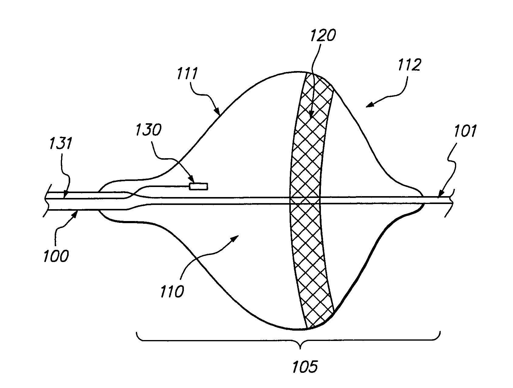
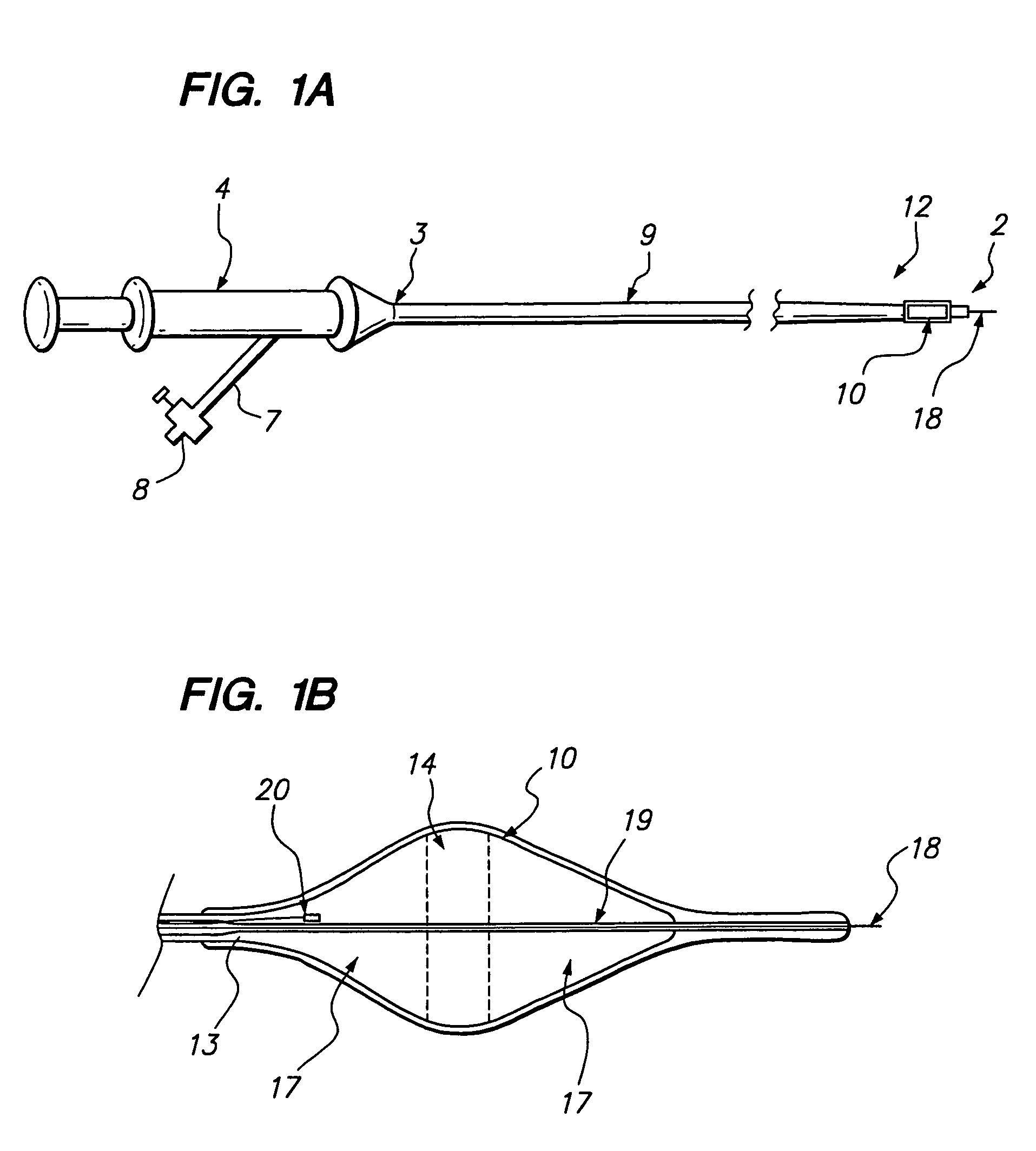
[0039]The balloons of this invention may be used with any balloon catheter of any design. A balloon catheter is shown generically in FIG. 1. It is understood that nothing in the figure is intended, nor is to be construed, to limit the scope of this invention in any manner whatsoever.

[0040]In FIG. 1A, catheter shaft 9 has a distal section 12 which contains deployable balloon 10, a shaft distal end 2 a shaft proximal end 3 and at least one lumen 13 extending between the two ends. Lumen 13 has at least one opening at the distal section 12 of the catheter shaft 9. Handle 4 is located at the proximal end of catheter shaft 9. The handle may contain means for controlling the movement of distal section 12 of shaft 9. Handle 4 may also include one or more hollow tubes 7, each having a proximal end, a distal end, a passageway and a locking valve 8 attached to it. Each such passageway is connected to one of the lumens 13 and is used to deliver and receive substances, in particular a working fl...


PUM

PropertyMeasurementUnit
tensile strengthaaaaaaaaaa
internal pressureaaaaaaaaaa

Abstract

The present invention relates to catheter balloons wherein the balloon are constructed of hydrophilic energy conductive polymers. It also relates to catheter balloons that self-anchor at a target site in a patient's body. Finally, it relates to catheter balloons with very small cross-sectional profiles at the distal end.

Description

[0001]The present invention relates to medical devices, in particular to balloons for use with balloon catheters.BACKGROUND OF THE INVENTION[0002]Balloon catheters are used in many medical procedures such as ablation, drug delivery, brachytherapy, chemotherapy, coronary angioplasty and thromboembolectomy. Regardless of whether the use to which the balloon catheter is being put involves transmitting substances, as in the case of chemotherapy or brachytherapy, or transmitting energy, as in the case of ablation, to a target site, it is preferred that the transmitting surface of the balloon be maintained in close contact with the target surface. At present, this most often involves careful application and control of pressure to the balloon by the operator from a location quite remote from the balloon. This generally requires substantial skill and, depending on the length of the procedure being applied, can be quite exhausting.[0003]Most balloon catheter uses require means for delivering...

Claims


Application Information

Patent Timeline
Patent Type & Authority Patents(United States)
IPC IPC(8): A61B18/18A61B18/14A61F2/958A61M25/00
CPCA61B18/1492A61M25/1029A61M25/10A61B2018/00214A61B2018/0022Y10T428/1345A61M25/1002
Inventor EBERL, GREGORY R.FORREST, MARK D.
Owner BOSTON SCI SCIMED INC
Why Eureka
Try Eureka