
Low profile shear pad and adapter

a low-profile, adapter technology, applied in the direction of axle-box mounting, railway components, axle-boxes, etc., can solve the problems of preventing a secure fit between the one car's coupler and the adjacent car's coupler, and existing trucks with standard side frames cannot be retrofitted with these thicker shear pads. , to achieve the effect of reducing the thickness of the adaptor

Active Publication Date: 2010-06-22
IDEAL IND INC +1
View PDF22 Cites 36 Cited by
  • Summary
  • Abstract
  • Description
  • Claims
  • Application Information

AI Technical Summary

Benefits of technology

The solution provides a low-profile mounting assembly that conforms to current performance standards without altering standard side frames, ensuring secure coupler fits and improved ride height consistency.

Problems solved by technology

Initially, such mounting assemblies included shear pads using metal wear surfaces which permitted limited lateral and longitudinal movement of the side frames relative to the roller bearing adapters positioned on the wheelsets.
While the shear pad described in the '933 patent and similar shear pads with multiple metal plate and rubber layers tend to have improved service life, a common problem is that they have a thickness of approximately one inch.
If one car is equipped with the thicker elastomeric shear pad and an adjacent car is not, the couplers will have different heights, thereby preventing a secure fit between the one car's coupler and the coupler of the adjacent car.
While this is practicable for a new truck, an existing truck having standard side frames cannot be retrofitted with these thicker shear pads.
This is especially problematic in view of recently heightened performance requirements from the American Association of Railroads, such as those outlined in AAR M-976.
The thinner shear pads that provide a proper ride height with standard mounting assemblies and side frames typically may not conform to the new performance standards, while thicker mounting assemblies that do conform to the new performance standards provide an improper ride height when coupled with cars having standard trucks.

Method used


Image

  • Low profile shear pad and adapter
  • Low profile shear pad and adapter
  • Low profile shear pad and adapter

Examples


Embodiment Construction

[0045]The embodiments disclosed herein are for the purpose of providing the required description of the present invention. These embodiments, however, are exemplary of the invention, which may be embodied in various forms. Therefore, specific details disclosed herein are not to be interpreted as limiting the invention as defined in the accompanying claims.

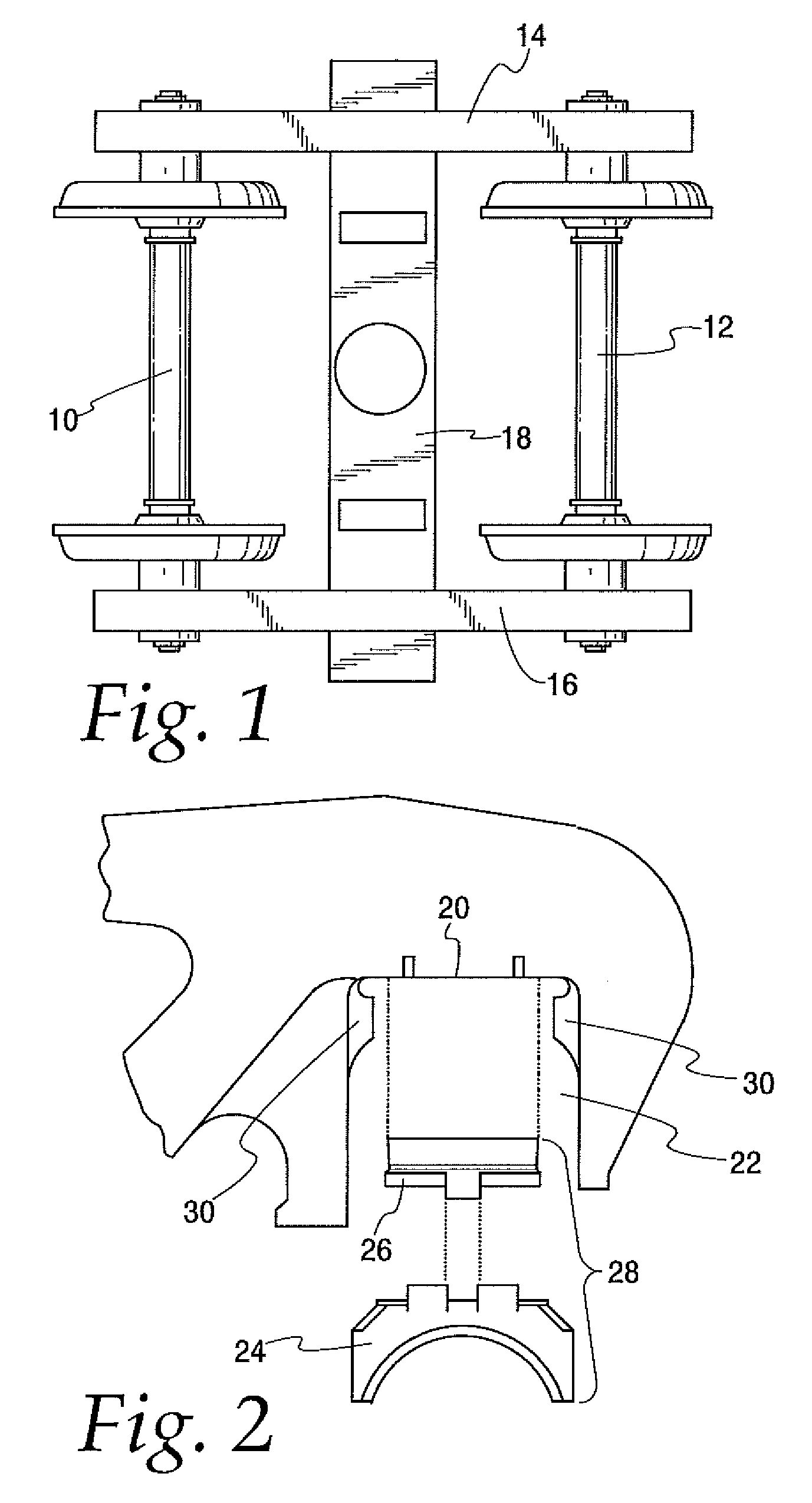
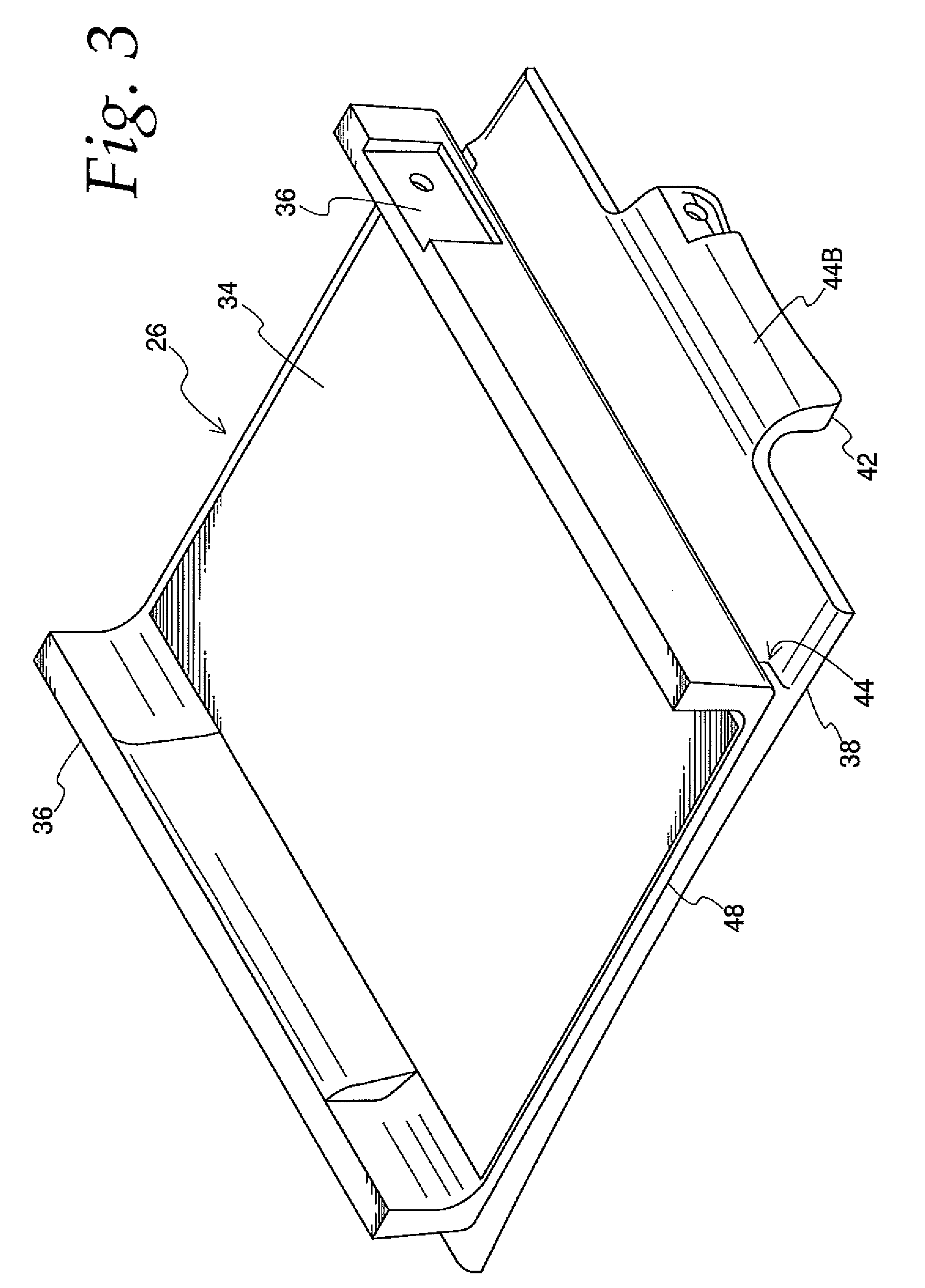
[0046]The present invention relates to a mounting assembly for use in mounting the side frames of a three-piece rail car truck to the roller bearings of the wheelsets. In FIG. 1, a conventional three-piece truck has wheelsets 10 and 12 upon which are supported side frames 14 and 16. A bolster 18 connects the side frames, as is conventional in rail car trucks of this design. The side frames include side frame pedestals 20 (FIG. 2) which define an opening 22. Within the opening 22 there will be located a metallic roller bearing adapter 24 and a shear pad assembly 26. Collectively the adapter 24 and shear pad 26 will be referred to he...


PUM


Abstract

A low profile mounting assembly for use between a rail car side frame pedestal and the rail car roller bearing includes a shear pad and a bearing adapter. In one embodiment, the shear pad has relatively thin plates joined by an elastomeric layer. In another embodiment, the shear pad includes a projection extending downwardly from a plate to be received and retained by a recess defined in a top surface of the adapter. In another embodiment, a central cavity formed in a lower plate of the shear pad cooperates with the adapter top surface to distribute forces on the roller bearing. In another embodiment, an elastomeric projection of a shear pad plate bears against ridges on the adapter top surface to prevent disengagement.

Description

BACKGROUND OF THE INVENTION[0001]1. Field of the Invention[0002]The present invention relates to a mounting assembly used in a railroad car truck and adapted to be positioned between a side frame pedestal and the roller bearing, and more specifically, to such a mounting assembly having a relatively low profile or thickness.[0003]2. Description of Related Art[0004]Mounting assemblies including a shear pad and mating roller bearing adapter have long been known in railroad car trucks for supporting the truck side frames on the wheelsets. Initially, such mounting assemblies included shear pads using metal wear surfaces which permitted limited lateral and longitudinal movement of the side frames relative to the roller bearing adapters positioned on the wheelsets. Subsequently, elastomeric mountings took the place of the metal wear surfaces to provide controlled flexibility in all directions, particularly for self-steering rail car trucks.[0005]U.S. Pat. No. 5,237,933, which is hereby inc...

Claims


Application Information

Patent Timeline
Patent Type & Authority Patents(United States)
IPC IPC(8): B61F5/26
CPCB61F5/305
Inventor EAST, DAVID M.SAMMARTINO, GIUSEPPEGOLEMBIEWSKI, RONALD D.
Owner IDEAL IND INC
Learn More