Wing structure for aircraft

a technology for aircraft wings and wing structures, which is applied in the direction of fuselages, transportation and packaging, and spars/stringers, etc., can solve the problems of reducing the buckled rib formed of a thin plate-shaped material, and the difficulty of compensating for the reduction of the so as to increase the buckling strength of the rib

Active Publication Date: 2010-06-22
AMERICAN HONDA MOTOR COMPANY
View PDF7 Cites 29 Cited by
  • Summary
  • Abstract
  • Description
  • Claims
  • Application Information

AI Technical Summary

Benefits of technology

[0008]The present invention has been achieved in view of the above-described circumstances, and has an object to increase the buckling strength of a rib against a shear load acting on the wing of an aircraft.
[0011]In a conventional structure, if stringer through holes through which stringers of upper and lower skins pass are formed on an upper edge and a lower edge of a rib which connects spars to each other, the buckling strength of the rib against a shear load caused by a lift or a drag of the wing is decreased due to the stringer through holes formed in the rib. Thus, a box structure of the wing comprising the spars, the skins, and the ribs is deformed, leading to a possibility that the shape of the airfoil is changed. However, in the arrangement of an embodiment of the present invention, the bead extending between the upper and lower stringer through holes is formed on the rib, and the upper and lower ends of the bead are formed into arcuate shapes so as to surround the upper and lower stringer through holes. Therefore, the buckling strength of the rib against the shear load is effectively enhanced, thereby suppressing the deformation of the wing.

Problems solved by technology

However, when a lift or a drag acts on the wing, there is a possibility that the rib formed of a thin plate-shaped material is buckled by a shear load.
However, it is difficult to compensate for the reduction in strength of the rib due to stringer through holes formed therein, merely by forming the bead extending in the vertical direction (wing thickness direction) on the rib.

Method used


Image

  • Wing structure for aircraft
  • Wing structure for aircraft
  • Wing structure for aircraft

Examples


Embodiment Construction

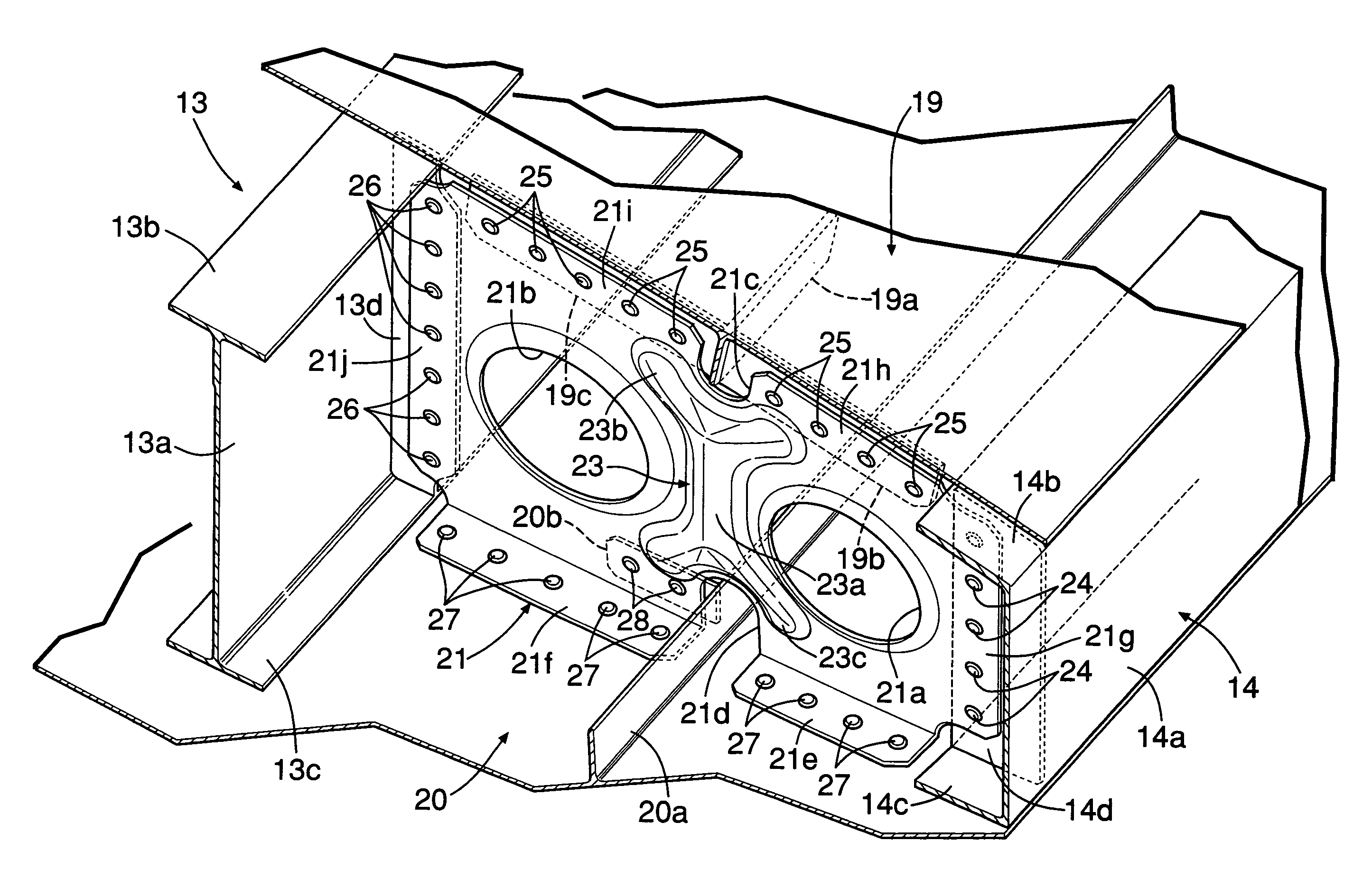
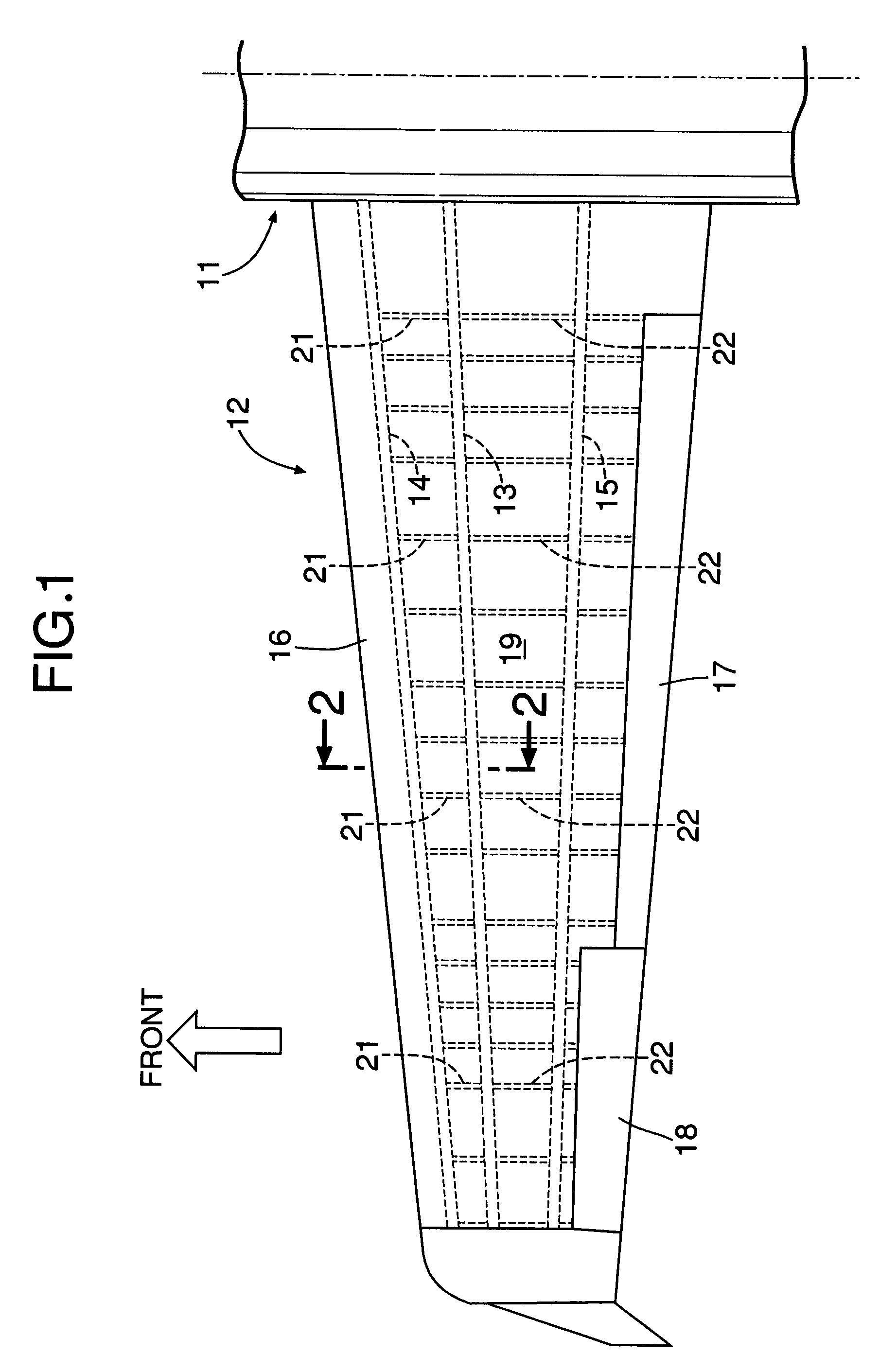
[0019]As shown in FIGS. 1 and 2, a main wing 12 is supported on a fuselage 11 of an aircraft, and includes a main spar 13 extending substantially in the span direction, a front spar 14 arranged in front of the main spar 13, and a rear spar 15 arranged in the rear of the main spar 13. A leading edge member 16 is fixed in front of the main spar 13. A flap 7 is oscillatably supported on a trailing edge part of the main wings 12 on an inner side in the span direction. An aileron 16 is oscillatably supported on the trailing edge part of the main wings 12 on an outer side in the span direction.

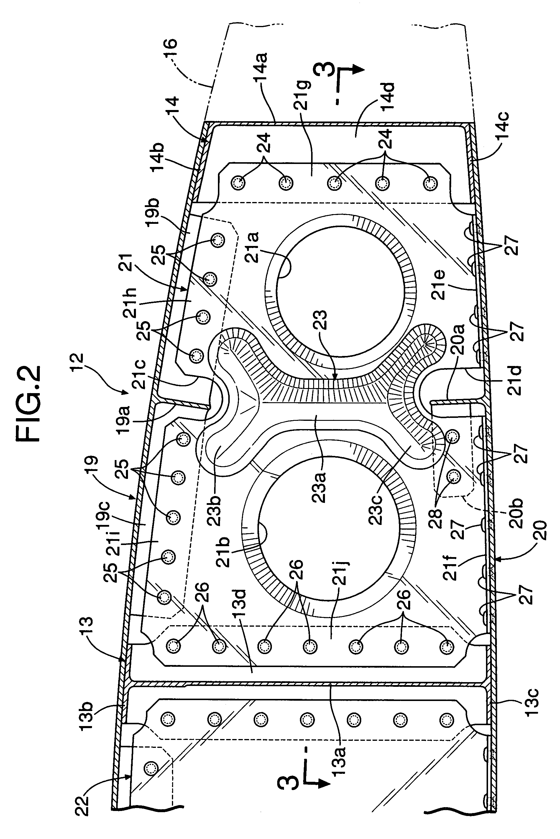
[0020]An upper skin 19, that defines the upper surface of the main wing 12, includes a plurality of stringers 19a formed integrally on the lower surface thereof in the span direction. A lower skin 20 that defines the lower surface of the main wing 12 includes a plurality of stringers 20a formed integrally on the upper surface thereof in the span direction.

[0021]The main spar 13 comprises a member ha...


PUM


Abstract

In a wing structure for an aircraft, a rib extends in a chord direction for connecting spars to each other with upper and lower stringer through holes through which stringers of skins pass being formed in upper and lower edges of the rib. A bead is formed on the rib so as to extend between the upper and lower stringer through holes. Upper and lower ends of the bead are formed into arcuate shapes so as to surround the upper and lower stringer through holes, respectively. Thus, it is possible to enhance the buckling strength of the rib against a shear load acting on the wing of the aircraft.

Description

CROSS-REFERENCE TO RELATED APPLICATIONS[0001]The present application claims priority under 35 USC 119 to Japanese Patent Application No. 2006-299008 filed on Nov. 2, 2006 the entire contents of which are hereby incorporated by reference.BACKGROUND OF THE INVENTION[0002]1. Field of the Invention[0003]The present invention relates to a wing structure of an aircraft, wherein a plurality of spars extend in a span direction; a plurality of stringers are arranged between the spars and extend in the span direction, a rib extends in a chord direction to connect the spars to each other and skins are provided for covering upper and lower surfaces of the spars, the stringers and the rib.[0004]2. Description of Related Art[0005]A wing structure of aircraft is known as described in Japanese Patent Application Laid-open No. 2002-302097 and Published Japanese Translation No. 2000-506816 of PCT Application No. PCT / US97 / 04550.[0006]More specifically, a rib defining the airfoil of an aircraft wing is...

Claims


Application Information

Patent Timeline
Patent Type & Authority Patents(United States)
IPC IPC(8): B64C3/18
CPCB64C3/18
Inventor NAMAIZAWA, MASAKIHASEGAWA, KAZUHIDENAKAZAWA, JUNAZUMA, HIROHIDE
Owner AMERICAN HONDA MOTOR COMPANY
Why Eureka
Try Eureka