Thread-tapping screw

a thread-tapping screw and thread-tapping technology, which is applied in the direction of thread-tapping fasteners, screws, fastening means, etc., can solve the problems of excessive removal of constructional components material, and achieve the effect of advantageous cutting-in and cutting behavior

Active Publication Date: 2010-06-22
HILTI AG
View PDF9 Cites 15 Cited by
  • Summary
  • Abstract
  • Description
  • Claims
  • Application Information

AI Technical Summary

Benefits of technology

[0012]In addition, the stepped arrangement of the cutting bodies, with which the section of the thread has a height that constantly decreases toward the free end of the shaft, insures a uniform tapping at the start of the screw-in process. As the cutting process is distributed between a plurality of arranged one after another cutting bodies, smaller peak pressures occur on the cutting bodies which at least partially project beyond the cross-sectional projection surface of the thread. This insures an advantageous profile of the undercut or counter-thread in a constructional component. The peak pressures on the cutting bodies, which locally can exceed the crushing strength of a mineral constructional component, lead to localized limited destruction of the constructional component which, in turn, leads to an excessive removal of the material of the constructional component, so that the thread, engageable in the produced undercut in this region, can transmit a limited load or no load at all. The inventive, thread-tapping screw has, in comparison with known screws, a smaller screw-in torque, a smaller setting time, and a high probability of being set even at smaller bore dimensions.
[0016]Advantageously, the cutting body has a polygonal cross-section, and at least one of the polygonal edges of the cutting body forms the radial outer profile of the cutting body. The so-formed cutting bodies have a particularly advantageous behavior in the constructional component. Advantageously, the cutting body has a shape close to the thread, wherein “close to the thread” means projecting at least partially beyond the cross-sectional projection surface of the thread. Advantageously, all of the cutting bodies have the same cross-sectional shape. That enables an easy manufacturing of the inventive screw. In an alternative embodiment, cutting bodies, which have different cross-sections, are provided on the thread.
[0018]Advantageously, a section of the thread the height of which constantly decreases toward the free end of the shaft, has from two to ten, preferably, three to six cutting bodies. This ensures an advantageous cutting-in and cutting behavior of the thread.
[0019]Advantageously, in an axial projection of the shaft, the cutting bodies are offset relative to each other, respectively, by from 60° to 120°, which ensures advantageous cutting-in and cutting behavior. The angle between the cutting bodies varies, dependent on the screw diameter.

Problems solved by technology

The peak pressures on the cutting bodies, which locally can exceed the crushing strength of a mineral constructional component, lead to localized limited destruction of the constructional component which, in turn, leads to an excessive removal of the material of the constructional component, so that the thread, engageable in the produced undercut in this region, can transmit a limited load or no load at all.

Method used


Image

  • Thread-tapping screw
  • Thread-tapping screw

Examples


Embodiment Construction

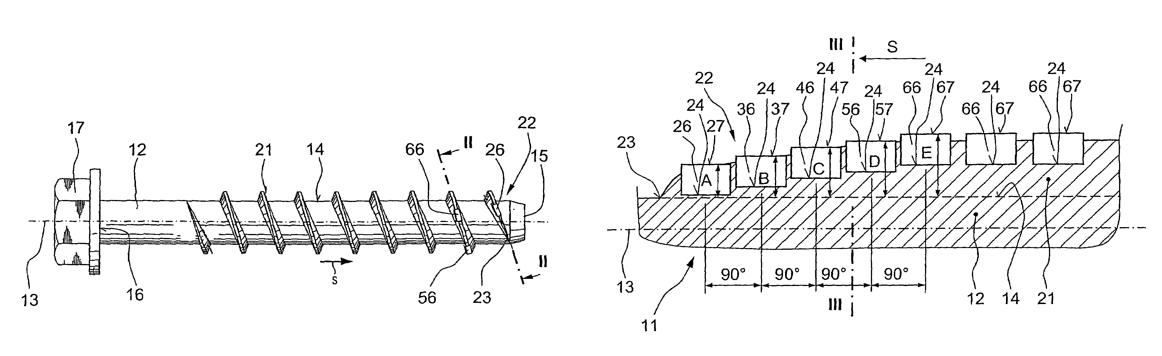
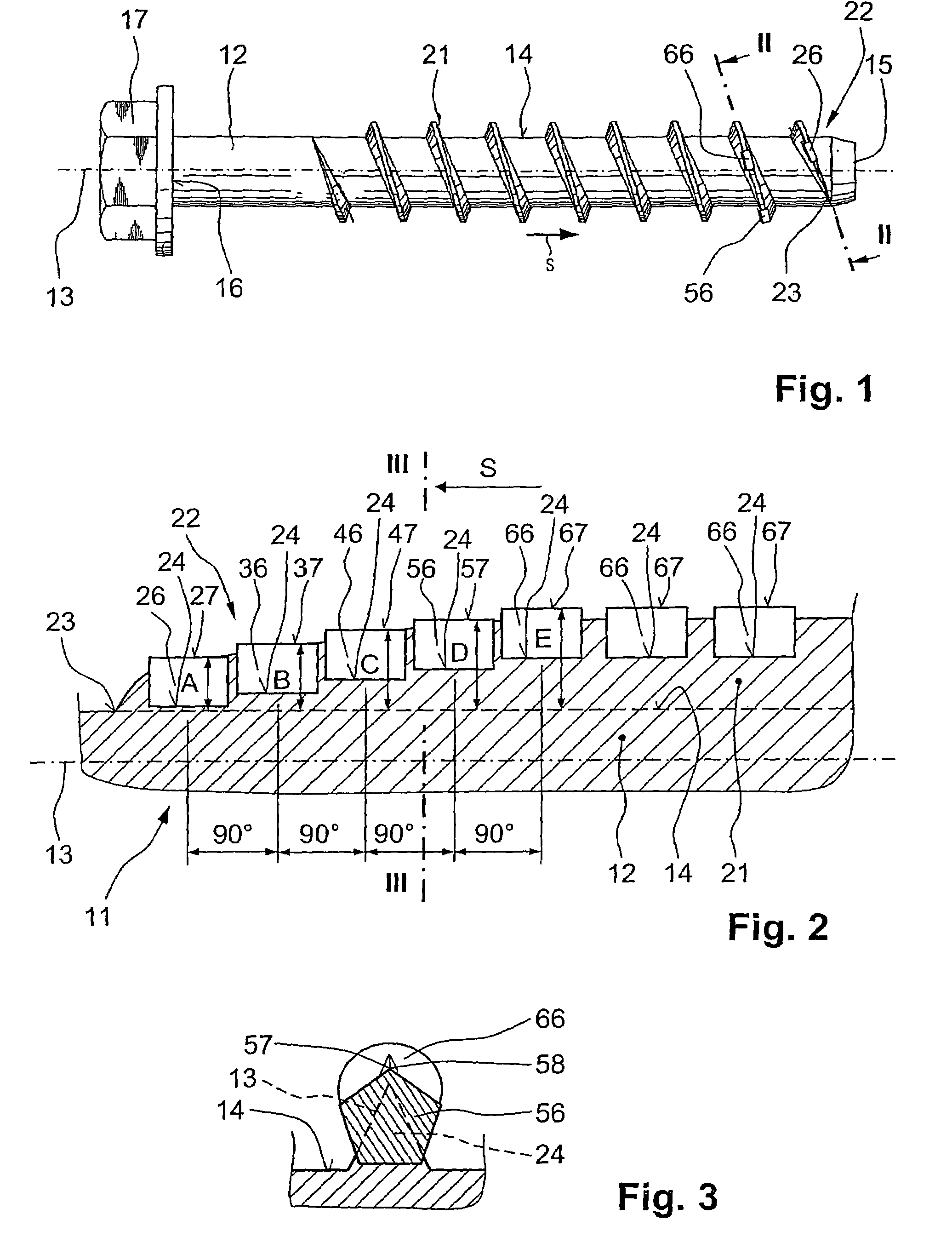
[0026]A screw 11 according to the present invention, which is shown in FIGS. 1 and 2, has a shaft 12 and a thread 21 formed integrally with the shaft 12 and extending, starting from the shaft free end 15, at least along a portion of the shaft length. The shaft 12 extends along a longitudinal axis 13 of the screw 11 and has a radially outer surface 14. At the end 16 of the shaft 12 opposite the free end 15, there is provided a hexagonal screw head that forms rotation-transmitting means 17. In the drawings the arrow S indicates the screw-in direction of the screw 11.

[0027]The thread 21 has a plurality of recesses 24 which opens radially outwardly and in which cutting bodies 26, 36, 46, 56, 66 are located. The cutting bodies 26, 36, 46, 56, 66 are formed of a material having a greater hardness then the hardness of the thread 21. A radial outer profile 27, 37, 47, 56, 67 of the cutting bodies 26, 36, 46, 56, 66 at least partially projects beyond the profile of the thread 21. The height ...


PUM


Abstract

A thread-tapping screw (11) has a thread (21) extending, starting from the screw shaft free end (15), at least along a portion of the shaft length and a height of which constantly decreasing toward the free end (15) of the shaft (12), and a plurality of cutting bodies (26, 36, 46, 56, 66) formed of a material having a greater hardness than hardness of the thread (21), located in recesses (24) formed in the thread (21) and opening radially outwardly and having, respectively, a radial outer profile (27, 37, 47, 57, 67) projecting, at least partially, beyond the thread and a height (A, B, C, D, E) of which decreases toward the free end (15) of the shaft (12) stepwise.

Description

BACKGROUND OF THE INVENTION[0001]1. Field of the Invention[0002]The present invention relates to thread-tapping screw having a shaft having a free end region, a thread extending starting from the screw shaft free end, at least along a portion of the shaft length, and a plurality of cutting bodies formed of a material having a greater hardness than hardness of the thread, located in recesses formed in the thread and opening radially outwardly and having, respectively, a radial outer profile projecting, at least partially, beyond the thread.[0003]2. Description of the Prior Art[0004]Screws which are described above, are screwed directly in a borehole that was preliminary formed in a constructional component, with the thread of the screw forming or tapping a counter-thread or an undercut in the constructional component.[0005]For outside applications, the screw, such as concrete screws, advantageously, are formed of a corrosion-resistant steel. However, steel materials often have a hard...

Claims


Application Information

Patent Timeline
Patent Type & Authority Patents(United States)
IPC IPC(8): F16B25/00
CPCF16B25/0052F16B25/0026
Inventor GSTACH, PETERAUMUELLER, BERTHOLD
Owner HILTI AG
Why Eureka
Try Eureka