Passively cooled computer

a computer and passive cooling technology, applied in the field of passive cooling computers, can solve the problems of insufficient power dissipation, limited power dissipation, and uncomfortable temperature of the cooling elements, so as to reduce thermal bridges, improve thermal decoupling of the units, and reduce the waste heat of the computer

Inactive Publication Date: 2010-06-22
KONTRON
View PDF17 Cites 35 Cited by
  • Summary
  • Abstract
  • Description
  • Claims
  • Application Information

AI Technical Summary

Benefits of technology

[0010]This makes it possible to dissipate the entire waste heat of the computer without active cooling, that is, in particular, without fans, such that the long term operating temperature equilibrium inside the computer remains low and in a range that is tolerable for constant operation. The vertical channel leading through the entire housing causes a chimney effect transporting the cooling air through the channel. This chimney effect, as a rule occurs with a channel length of more than twenty centimeters (the term “vertical” is, throughout the entire application, used in relation to the computer in its operating position).
[0011]The cooling bodies preferably substantially separate the air channel from the remaining volume inside the housing frame. This causes the cooling air to come into contact with only the cooling surfaces of the cooling bodies. Since a closed cooling channel is provided, that is, there are no air holes in the housing or in the cooling bodies, damage by parts falling into the computer is eliminated.
[0013]This invention allows for dissipation of the waste heat of a computer of typical power passively, that is, without fans, and without having to substantially limit the power of the computer and its components, in particular the processor, mass storage, power supply etc.
[0014]The housing frame preferably constitutes the carrying frame, on which the components or units of the computer such as processor(s), volatile memory (RAM), mass storage devices such as hard discs, CD and / or DVD-drives, interface adapters, power supply and / or batteries are mounted. The housing frame preferably is made of thin sheet metal parts, preferably with a thickness of less than one millimeter. This improves the thermal decoupling of the units having different temperatures. In order to further reduce thermal bridges between different housing sections, optional metallic cladding elements are arranged outside the housing frame, covering at least one side surface of the housing frame, and being distanced from the housing frame by an air gap.
[0015]At the top of the housing, a cladding that is permeable by air can be arranged, exhibiting (seen in a horizontal direction) a round or convex cross section. This prevents users from depositing objects on the housing and thereby obstructing the air channel.
[0022]In a further preferred embodiment of the invention, an insulation layer is arranged between at least one pair of cooling bodies that oppose one another. Thus, this layer extends in parallel and in-between the cooling bodies and extends substantially over the entire opposing surfaces of the two cooling bodies. In this manner the cooling bodies are decoupled from one another with respect to infrared radiation, and almost not heat exchange between the cooling bodies will take place. This allows arrangement of components and cooling bodies with different temperatures opposite one another without the hotter cooling body heating up the cooler one.

Problems solved by technology

However, the temperature of the cooling elements can become uncomfortable, and the power that can be dissipated is limited.
The known solutions do not provide for sufficient dissipation of power for the various different components of the computer.
Thus, the processing power of modern processors cannot be made use of.

Method used


Image

  • Passively cooled computer
  • Passively cooled computer
  • Passively cooled computer

Examples


Embodiment Construction

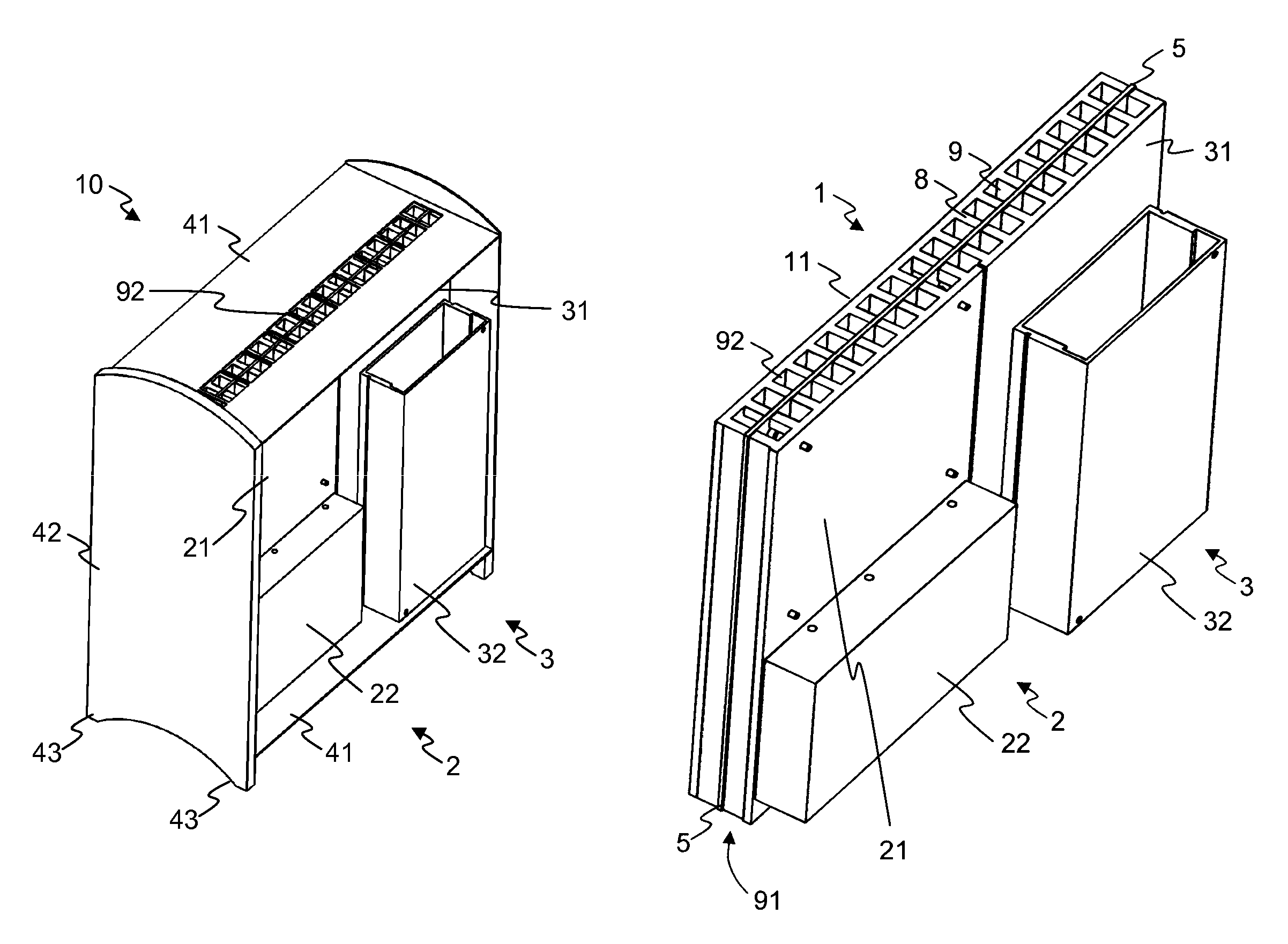
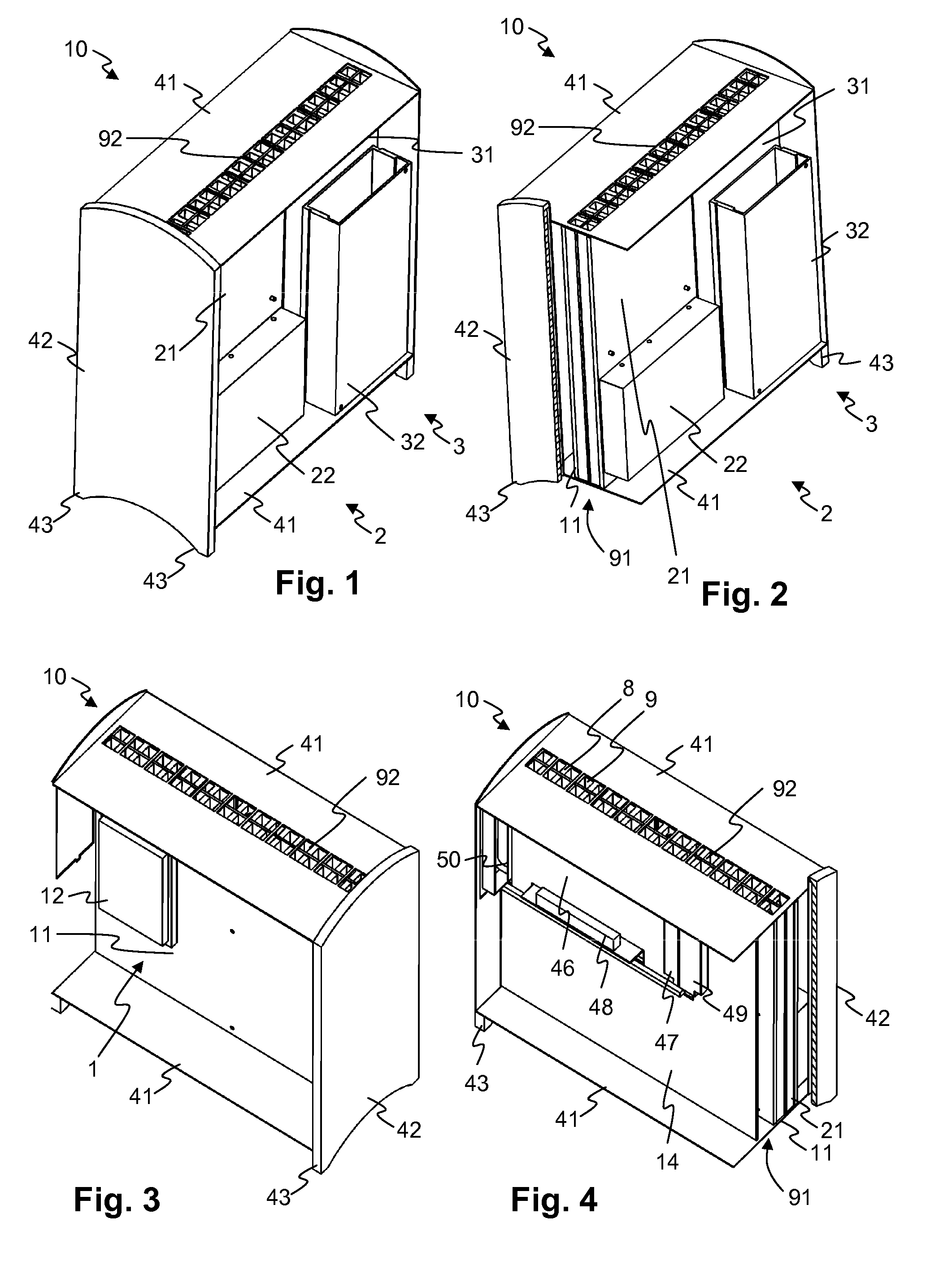
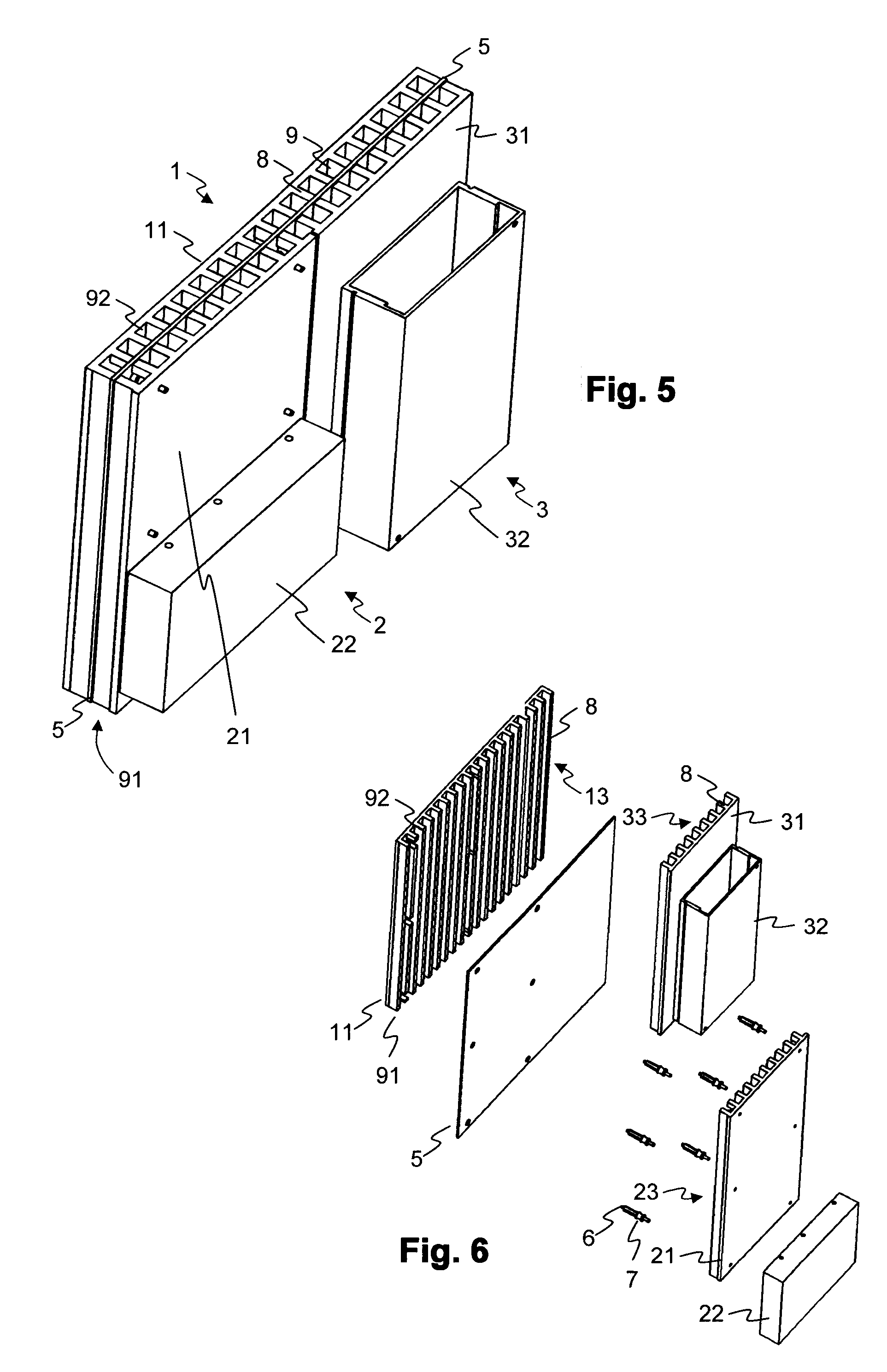
[0032]The main elements of a computer cooled according to the invention are shown in FIGS. 1 to 4. The computer is shown in its operating condition, that is, with vertically oriented cooling channels. The main elements of the cooling arrangement alone are shown in FIGS. 5 to 7.

[0033]The computer 10 comprises several units 1, 2, 3 which are arranged in a housing 4 with a load carrying housing frame 41:[0034]A processor unit 1 with one or more processors 12 and further elements typically arranged on a motherboard of a computer. The processor 12 and optionally also some of the further elements are thermally coupled to a processor cooling body 11, for example by mechanically pressing them against one another, with a thermally conductive material placed in-between for bridging gaps. The processor cooling body 11 is, in a border area, attached to the housing frame 41.[0035]A hard disk unit 2 with one or more hard disks 22. The hard disk unit(s) 2 are thermally coupled to a hard disk cooli...


PUM


Abstract

A passively cooled computer includes two or more components arranged in a housing frame 41, wherein each of these components is associated with a cooling body for dissipating waste heat of the component when the component is in operation. The cooling bodies each include a cooling surface, and these cooling surfaces are arranged to oppose one another with their cooling surfaces and thereby define an air channel leading vertically through the inside of the housing frame. The cooling bodies substantially separate the air channel from the remaining volume inside the housing frame.

Description

BACKGROUND OF THE INVENTION[0001]The invention relates to electrical and electronic data processing devices, in particular to a passively cooled computer[0002]Such a computer is described in U.S. Pat. No. 7,095,611. The housing cover and floor of this computer are shaped as cooling elements. Internally, the computer is separated in an upper, hot compartment, and a lower, cooler compartment. Components with a larger heat loss, for example the processor, are arranged in the upper compartment. However, the temperature of the cooling elements can become uncomfortable, and the power that can be dissipated is limited.[0003]U.S. Pat. No. 5,671,120 shows a personal computer, in which one side of the housing is configured to be a cooling body cooling the processor. The other sides of the housing consist of perforated plates which allow for an air flow through the entire inner volume of the housing. The openings in the side walls allow for objects to fall in and damage the computer.[0004]U.S....

Claims


Application Information

Patent Timeline
Patent Type & Authority Patents(United States)
IPC IPC(8): H05K7/20F28F7/00
CPCG06F1/20G06F1/181
Inventor KUNZ, FELIX
Owner KONTRON
Why Eureka
Try Eureka