Supercharge Your Innovation With Domain-Expert AI Agents!

Control unit

a technology of control unit and control arm, which is applied in the direction of program control, fluid pressure measurement by mechanical elements, special data processing applications, etc., can solve the problems of damage to the motor driving the main shaft or the robot arm may be unexpectedly collided with other objects, and the operation information of the machine tool can be relatively easily acquired

Inactive Publication Date: 2010-06-22
FANUC LTD
View PDF10 Cites 4 Cited by
  • Summary
  • Abstract
  • Description
  • Claims
  • Application Information

AI Technical Summary

Benefits of technology

The present invention provides a control unit for a machine tool that can detect and analyze vibrations in real-time to prevent collisions and improve operational efficiency. The control unit includes a vibration detection system attached to the main shaft or movable body of the machine tool, a storage system for storing vibration signals related to the machine tool's operation, and a collision judgment system for determining if a collision has occurred based on the vibration signals and operation information. The control unit can also include a position and speed detection system for accurately determining the position and speed of the main shaft or movable body at the time of collision. Additionally, the control unit can set the appropriate threshold value based on the machine tool's operation information or type of workpiece machined. Overall, the control unit helps to prevent collisions, improve operational efficiency, and enhance the machine tool's performance.

Problems solved by technology

A main shaft of a machine tool or an arm of a robot may unexpectedly collide with other objects due to a program error or an error in operation made by an operator in some cases.
In the case of a collision, the main shaft or the robot arm, and a motor for driving the main shaft or the robot arm may be damaged.
In this case, machining and operation accuracy are affected.
Since the main shaft and the motor to drive the main shaft are abnormally vibrated when the main shaft of the machine tool etc., is damaged, an abnormal vibration is detected by a position detector provided on the main shaft.
However, in the case where the machine tool is automatically operated, specific circumstances at the time of collision are unknown.
Therefore, it is difficult to determine a cause of the collision.
Even when the machine tool is manually operated by an operator, unless the operator reports that the collision has occurred, it is also difficult to determine the cause of the collision, since the specific circumstances at the time of collision are unknown.

Method used


Image

  • Control unit
  • Control unit
  • Control unit

Examples


Embodiment Construction

[0026]Referring to the accompanying drawings, an embodiment of the present invention will be explained below. In the following drawings, like reference numerals have been used throughout to designate similar elements. In order to facilitate understanding, various reduced scales are used in the drawings.

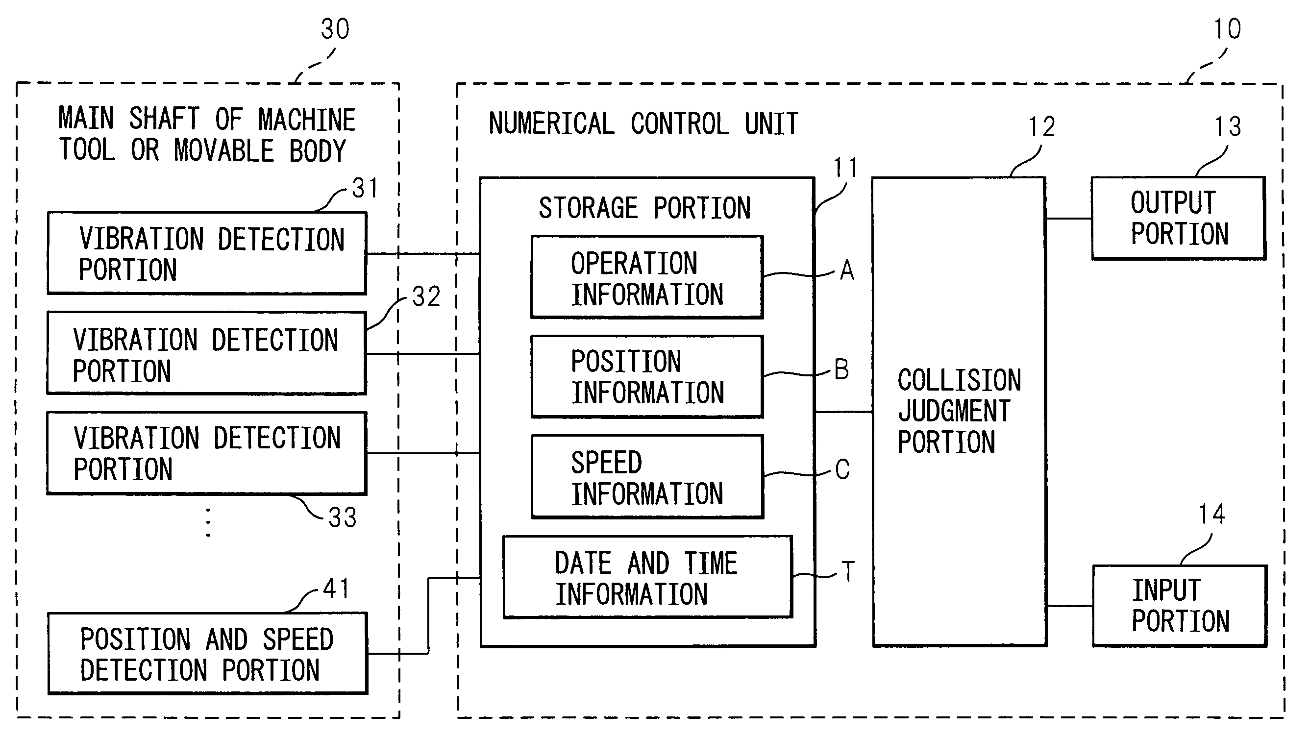
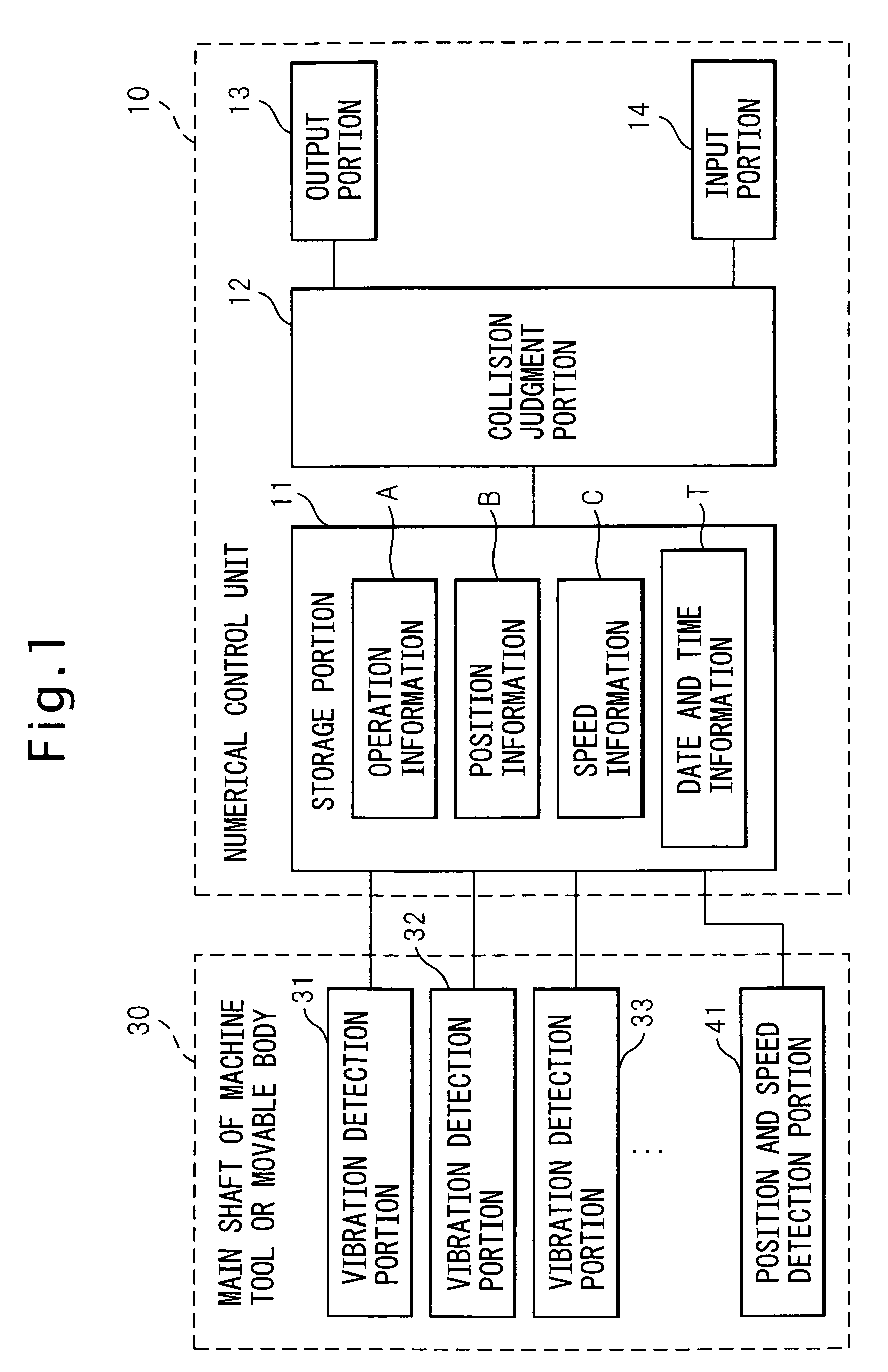
[0027]FIG. 1 is an arrangement view showing a control unit of the present invention. A main shaft 30 of a machine tool 30 or a robot arm is connected to a control unit, for example, a numerical control unit 10 shown in FIG. 1. Numerical control unit 10 may be connected to a movable body which moves relative to the main shaft of the machine tool, for example, numerical control unit 10 may be connected to a table (not shown) for holding a workpiece. In this specification, “the main shaft 30 or others” used in the following description means two cases. One is a case in which numerical control unit 10 is connected to main shaft 30 and the other is a case in which numerical control unit 10...


PUM


Abstract

A control unit for a machine tool at least one vibration detection device attached to a main shaft portion of a machine tool or a movable body; a storage device for storing a vibration signal detected by the vibration detection device being related to operation information of the machine tool; a collision judgment device for judging that a collision has occurred; and an output device for outputting the vibration signal at the time of judging the occurring of the collision. By the above constitution, the control unit is capable of grasping a specific circumstance of collision and quickly determining a cause of collision.

Description

BACKGROUND OF THE INVENTION[0001]1. Field of the Invention[0002]The present invention relates to a control unit. More specifically, the present invention relates to a control unit having a collision judgment function for judging that a main shaft of a machine tool has collided with other objects.[0003]2. Description of the Related Art[0004]A main shaft of a machine tool or an arm of a robot may unexpectedly collide with other objects due to a program error or an error in operation made by an operator in some cases. In the case of a collision, the main shaft or the robot arm, and a motor for driving the main shaft or the robot arm may be damaged. In this case, machining and operation accuracy are affected. Therefore, when a collision occurs, it is desirable that the machine tool or the robot be stopped and checked.[0005]According to Japanese Unexamined Patent Publication No. 2-179479, the following countermeasure is disclosed. Since the main shaft and the motor to drive the main shaf...

Claims


Application Information

Patent Timeline
Patent Type & Authority Patents(United States)
IPC IPC(8): G06F19/00G05B11/01G06F17/40G01F17/00G05B9/02G05B19/18
CPCG05B19/4061G05B2219/37634
Inventor MASUYA, MICHIOKA, HIDEKIFUKUDA, MASAMOTO
Owner FANUC LTD
Features
  • R&D
  • Intellectual Property
  • Life Sciences
  • Materials
  • Tech Scout
  • Unparalleled Data Quality
  • Higher Quality Content
  • 60% Fewer Hallucinations
Learn More