Seals and a method of making seals

a technology of sealing and sealing plate, applied in the field of sealing plate, can solve the problems of reducing the acceptability of the sealing plate provided, affecting the operation of rotating components, and affecting the sealing effect, and achieve the effect of flexibleness

Inactive Publication Date: 2010-06-29
ROLLS ROYCE PLC
View PDF5 Cites 10 Cited by
  • Summary
  • Abstract
  • Description
  • Claims
  • Application Information

AI Technical Summary

Benefits of technology

[0006]Alternatively, in accordance with the present invention, there is provided a seal comprising an edge to be held in close proximity to a rotating surface in use, the edge being reinforced by creases extending away from the edge, the seal characterised in that between the creases the edge includes slots to facilitate flexibility in the edge when held in close proximity to the rotating surface.
[0011]Preferably, the slots extend substantially perpendicular to the major axis of the edge. Typically, the slots terminate in a keyhole or bulbous end to inhibit crack propagation caused by flexing. Advantageously, the slots are of varying length extending away from the edge. Normally, the slots will have a length at least equivalent to the wear depth in use of a seal.
[0015]Alternatively, in accordance with the present invention there is provided a method of forming a seal element including the steps of taking a length of material and forming a number of creases to define a seal edge and characterised in that slots are formed in the length of material which when the seal is formed extend from the seal edge to render that edge more flexible.

Problems solved by technology

Furthermore, there may be significant accommodation and packaging problems within an engine in terms of the space available to accommodate the seal but nevertheless good sealing is required during rotating component excursions and misalignments during operations.
The folds provide a degree of reinforcement but nevertheless the shaft can engage in a number of excursions and mis-alignments which diminish the acceptability of the seal provided.
A brush seal essentially comprises bristles which extend towards the relative rotating component and provide the desired seal but are subject to wear and non-ideal sealing / support for the rotating component in operation.

Method used


Image

  • Seals and a method of making seals
  • Seals and a method of making seals
  • Seals and a method of making seals

Examples


Embodiment Construction

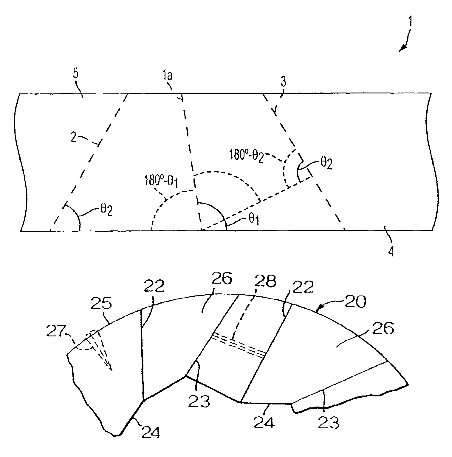
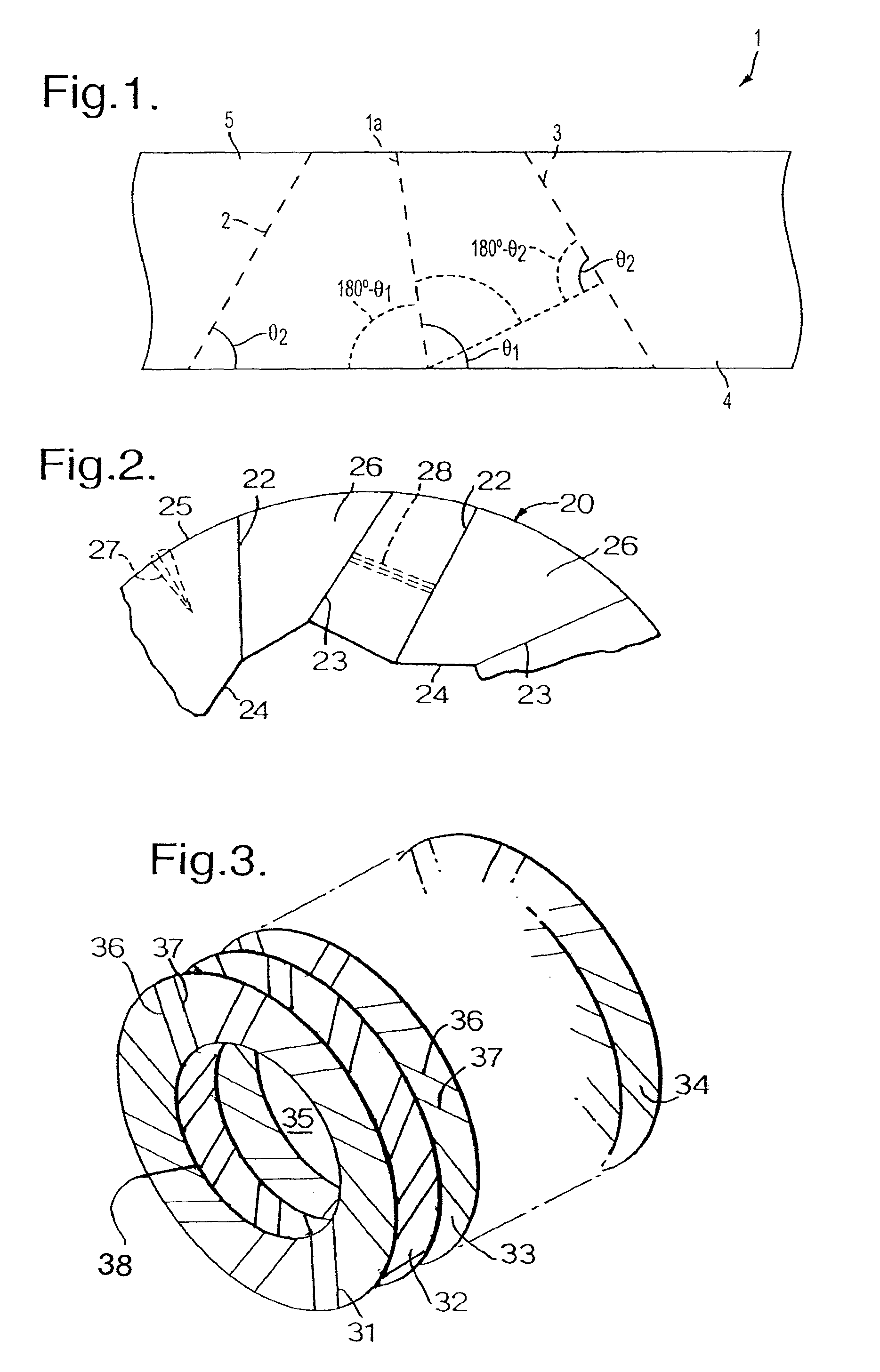
[0029]FIG. 1 illustrates a section of material 1 such as steel or a nickel alloy from which a seal in accordance with the present invention is formed. The length of material 1 is folded to create a set of forward folds 2 and a set of backward folds 1a, and 3 such that the creases formed about these folds 1a, 2, 3 create a ring or disc for location about or on a rotating shaft in use. It will be appreciated that the choice of angles Θ1. Θ2 for the folds 1a, 2, 3 and therefore the creases in the length of material 1 essentially determine the curvature of the ring formed.

[0030]Furthermore, the number of creases formed by folds 1a, 2, 3 will create greater iterative curvature in the material 1 and so closer proximity for an inner or sealing edge 4 to a desired curvature for consistency with that of a rotating component. In short, in side view the material 1 appears to be kinked about the folds 1a, 2, 3 into the desired ring formation to form a seal in accordance with the present inventi...


PUM


Abstract

A seal and method of making seals utilizes folds in order to form creases in a length of material such that the creases reinforce individual seal elements or surfaces while perforations or slots in a seal edge allow air leakage from one side of the seal element or surface to the other. Thus, air pressurization can take place between spaced seal elements or surfaces and this allows air flotation or riding of a rotating component relative to a static housing component. The perforations are typically graduated from the seal edge in order to provide the best pressurization and air-riding effect for proximity or gap control between the sealing edge and the rotating component surface. The slots effectively provide flexibility to the sealing edge such that the seal component emulates a brush seal.

Description

CROSS REFERENCE TO RELATED APPLICATION[0001]This application is a continuation in part of application Ser. No. 10 / 630,836 filed Jul. 31, 2003 and now abandoned, which claims priority to GB 0219781.2, filed Aug. 23, 2002.FIELD OF THE INVENTION[0002]The present invention relates to seals and more particularly to seals used between a static part and a rotating part such as a shaft in an engine.[0003]Seals, and in particular air seals, are required within gas turbine engines between static and rotating components. Typically, the seals prevent leakage of cooling air from regions of high pressure to regions of low pressure. Clearly, the seals must be able to withstand and cope with the differential pressure across the seal from the region of high pressure on one side to the region of low pressure on the other. Furthermore, there may be significant accommodation and packaging problems within an engine in terms of the space available to accommodate the seal but nevertheless good sealing is ...

Claims


Application Information

Patent Timeline
Patent Type & Authority Patents(United States)
IPC IPC(8): F16J15/44F16J15/447
CPCF01D11/003F16J15/3228F16J15/445F16J15/4472F16J15/3292F05D2240/56
Inventor MCMILLAN, ALISON J
Owner ROLLS ROYCE PLC
Why Eureka
Try Eureka