Jet-propulsion personal watercraft

a technology of jet propulsion and personal watercraft, applied in the direction of marine propulsion, special-purpose vessels, vessel construction, etc., to achieve the effect of effective steering

Inactive Publication Date: 2010-06-29
KAWASAKI HEAVY IND LTD
View PDF3 Cites 6 Cited by
  • Summary
  • Abstract
  • Description
  • Claims
  • Application Information

AI Technical Summary

Benefits of technology

[0005]The present invention addresses the above described conditions, and an object of the present invention is to provide a jet-propulsion personal watercraft which is capable of being effectively steered for a longer time period in a deceleration state of the watercraft, without making a driver feel driving discomfort.

Problems solved by technology

However, in the above described conventional jet-propulsion personal watercraft, when the driver operates the throttle lever to close the throttle valve, the throttle valve is quickly closed under the force applied from the return spring up to a position at which the actuator restricts the closing operation of the throttle valve and then the actuator abruptly restricts the closing operation of the throttle valve.

Method used


Image

  • Jet-propulsion personal watercraft
  • Jet-propulsion personal watercraft
  • Jet-propulsion personal watercraft

Examples


embodiment 1

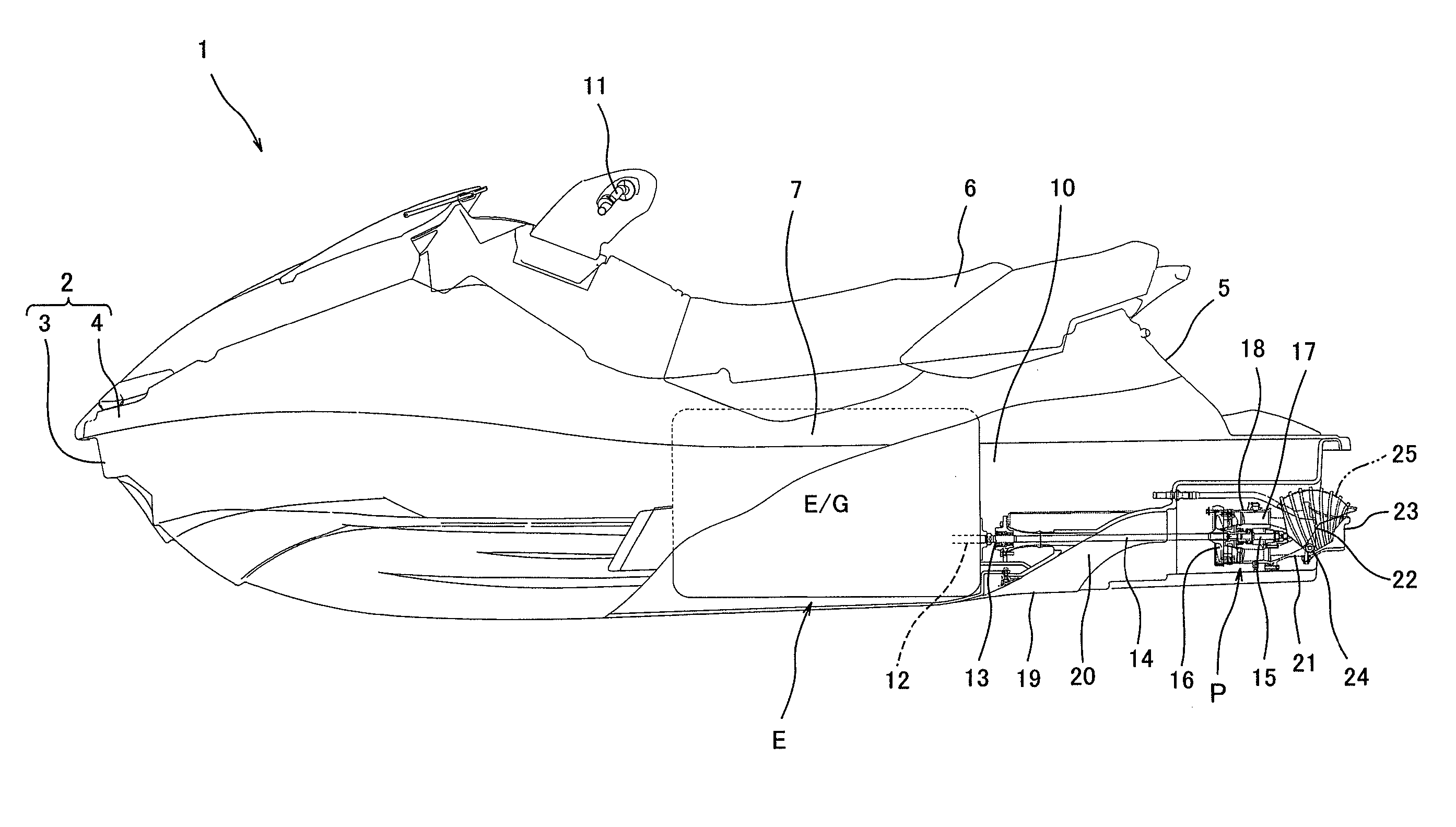
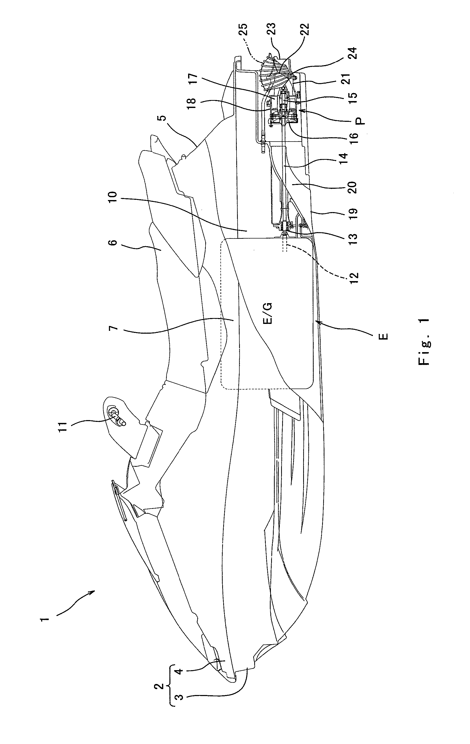
[0055]FIG. 1 is a partially cutaway side view of a jet-propulsion personal watercraft 1 as seen from the left. With reference to FIG. 1, the jet-propulsion personal watercraft 1 is a straddle-type jet-propulsion watercraft which is provided with a seat 6 straddled by a driver. A body 2 of the watercraft 1 comprises a hull 3 and a deck 4 covering the hull 3 from above. A center portion (protruding portion) 5 in a width direction of a rear part of the deck 4 protrudes upward. The seat 6 is mounted over an upper surface of the protruding portion 5. A deck floor 7 is formed on right and left sides in the width direction of the protruding portion 5 to be substantially flat and lower than the protruding portion 5 to enable a driver's feet to be put thereon.

[0056]A space defined by the hull 3 and the deck 4 below the seat 6 forms an engine room 10 which accommodates the engine E. The engine E is mounted in the engine room 10 in such a manner that a crankshaft 12 extends in a longitudinal d...

embodiment 2

[0088]A second embodiment will now be described. In the second embodiment, the same reference numerals as those of the first embodiment are used to denote the same or corresponding components which will not be further described. FIG. 10 is a schematic view of a throttle system 60 in a jet-propulsion personal watercraft according to a second embodiment of the present invention. As shown in FIG. 10, the throttle system 60 includes a known throttle body 61 configured to control an amount of air taken in from outside and supplied to the engine E (see FIG. 1) by opening and closing butterfly throttle valves 62. The bypass valve in the first embodiment is omitted in the throttle system 60 in the second embodiment. The throttle valves 62 are fixed to a rotatable throttle shaft 63. A return spring 64 is mounted on one end portion of the throttle shaft 63 and is configured to apply a force to return the throttle shaft 63 in a direction to close the throttle valves 62 in a state where a force...


PUM


Abstract

A jet-propulsion personal watercraft includes an engine configured to generate a driving power for generating a propulsion force to propel the watercraft, an engine speed changing system configured to be able to change an engine speed of the engine, a determiner configured to determine whether or not to execute control for effectively steering the watercraft at start of deceleration, and an engine controller configured to control the engine speed changing system based on information received from the determiner. The engine controller is configured to, when the determiner determines that the control for effectively steering the watercraft should not be executed, control the engine speed changing system so that a decrease rate of the engine speed immediately after the determination is smaller than a decrease rate of the engine speed in a case where the determiner determines that the control for effectively steering the watercraft should not be executed.

Description

TECHNICAL FIELD[0001]The present invention relates to a jet-propulsion personal watercraft configured to eject a water jet by an engine driving power to generate a propulsion force for propelling the watercraft.BACKGROUND ART[0002]In recent years, jet-propulsion personal watercraft (PWC) have been widely used in leisure, sport, rescue activities, and the like. The watercraft is typically equipped with an engine in an engine room in an inner space defined by a hull and a deck forming a body. The engine drives a water jet pump, which pressurizes and accelerates water sucked from a water intake generally provided on a hull bottom surface and ejects it rearward from an outlet port. As the resulting reaction, the watercraft is propelled forward.[0003]For example, when making such a watercraft approach a position parallel to a shoreline, a driver must steer a steering handle while manipulating a throttle lever to control a propulsion force for turning the body. A conventional jet-propulsi...

Claims


Application Information

Patent Timeline
Patent Type & Authority Patents(United States)
IPC IPC(8): B63H21/22
CPCB63H21/213B63B35/731B63B34/10F02D9/1055
Inventor OZAKI, ATSUFUMIWATABE, SATORU
Owner KAWASAKI HEAVY IND LTD
Why Eureka
Try Eureka