Manifold assembly

a manifold and assembly technology, applied in the direction of liquid transfer devices, instruments, volume meters, etc., can solve the problems of inability to accurately and precisely control the conduit, the inability to clean up spills, and the inability to accurately control the conduit, etc., to achieve the effect of precise tolerances

Active Publication Date: 2010-06-29
SAKURA FINETEK U S A
View PDF232 Cites 134 Cited by
  • Summary
  • Abstract
  • Description
  • Claims
  • Application Information

AI Technical Summary

Benefits of technology

[0007]The present invention alleviates to a great extent the disadvantages of the known automated tissue processing systems by providing a manifold assembly in which fluid conduits are etched directly into the manifold. The manifold is preferably formed of two pieces of corrosion resistant, polymeric material. Each piece of material has matching channels etched therein. According to an embodiment of the present invention, channels are machined into each piece of the manifold. When the pieces are joined together conduits are created with the channels facing each other such that fluid may traverse a length of the manifold. The pieces may be joined by, for example, clamping, binding, welding or other known mechanically fastening technique. One advantage to etching two pieces of material to form a conduit by joining the pieces, is that precise tolerances for the conduit may be achieved.

Problems solved by technology

There are various disadvantages of known systems.
For example, manually pouring into, or draining, reagent vats suffers a disadvantage being time consuming and requiring pouring accuracy, decreasing the overall efficiency of the tissue processing system.
Another disadvantage is that manually pouring and draining reagents is that it can be sloppy, requiring clean-up of spills and consequential instrument down-time.
A further disadvantage is that selecting the correct reagent requires operator attention and accuracy and there is an increased possibility of reagent application errors, decreasing test accuracy and decreasing operational efficiency.
In an automated system, there also are disadvantages.
Such systems suffer various drawbacks such as the amount of effort required to set up and dispense the reagents, the possibilities of evaporation during processing or contamination and difficulties in handling minute quantities of large numbers of reagents.

Method used


Image

  • Manifold assembly
  • Manifold assembly
  • Manifold assembly

Examples


Embodiment Construction

[0032]In the following paragraphs, the present invention will be described in detail by way of example with reference to the figures. Throughout this description, the preferred embodiment and examples shown should be considered as exemplars, rather than as limitations on the present invention. As used herein, the “present invention” refers to any one of the embodiments of the invention described herein, and any equivalents. Furthermore, reference to various feature(s) of the “present invention” throughout this document does not mean that all claimed embodiments or methods must include the referenced feature(s).

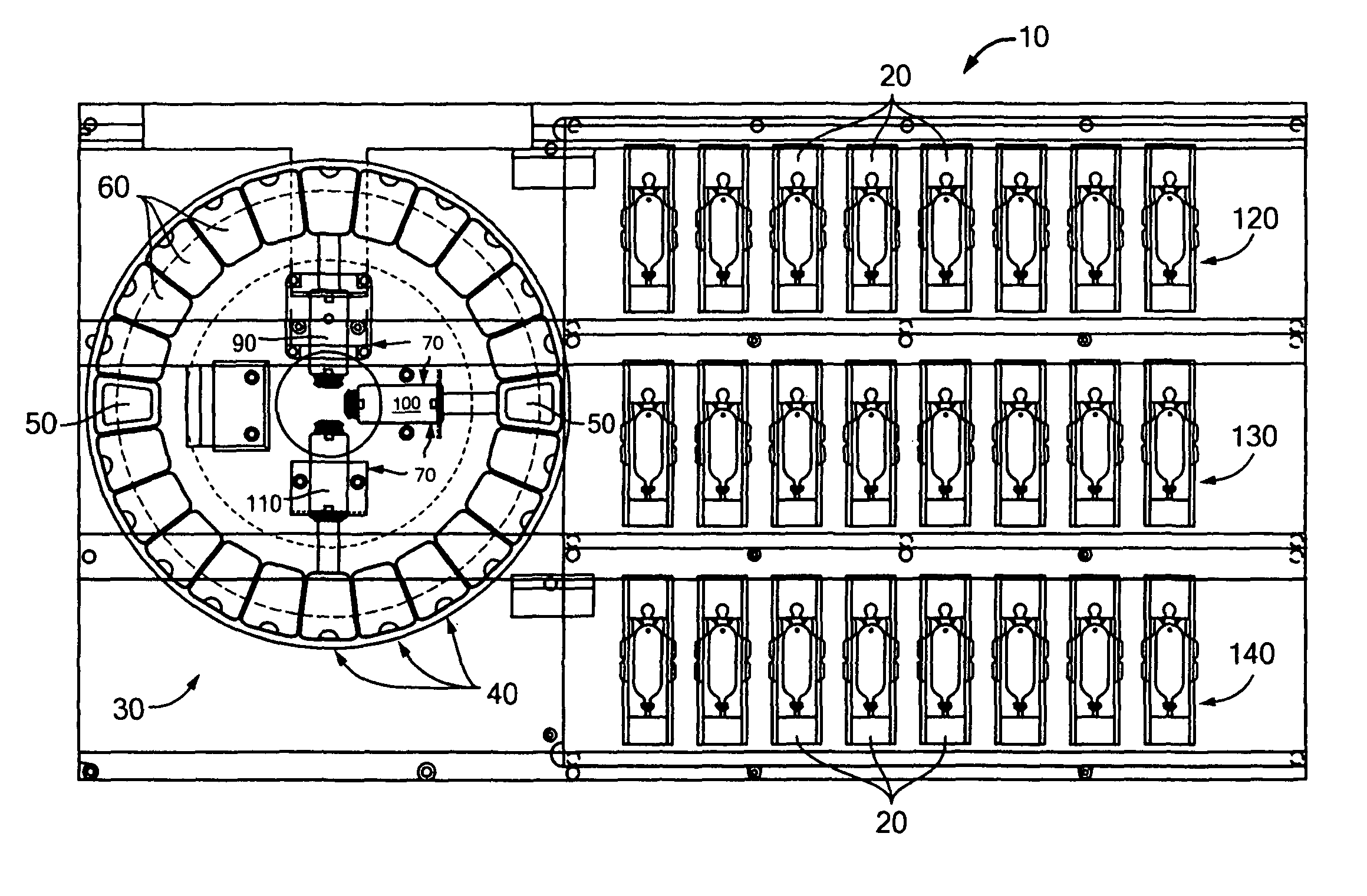
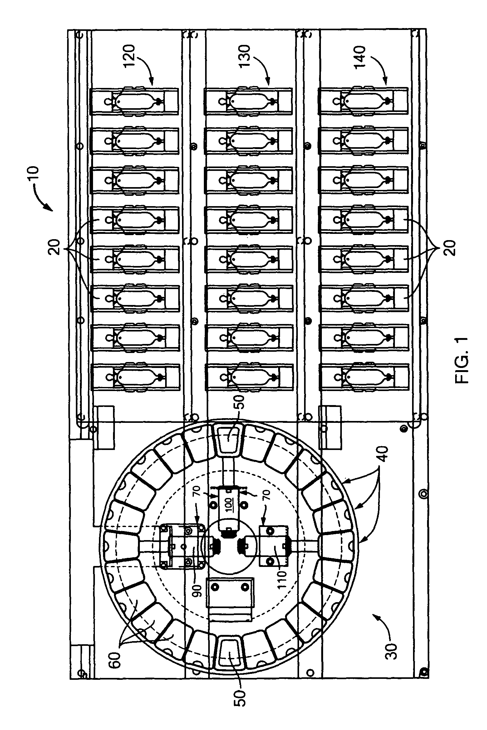
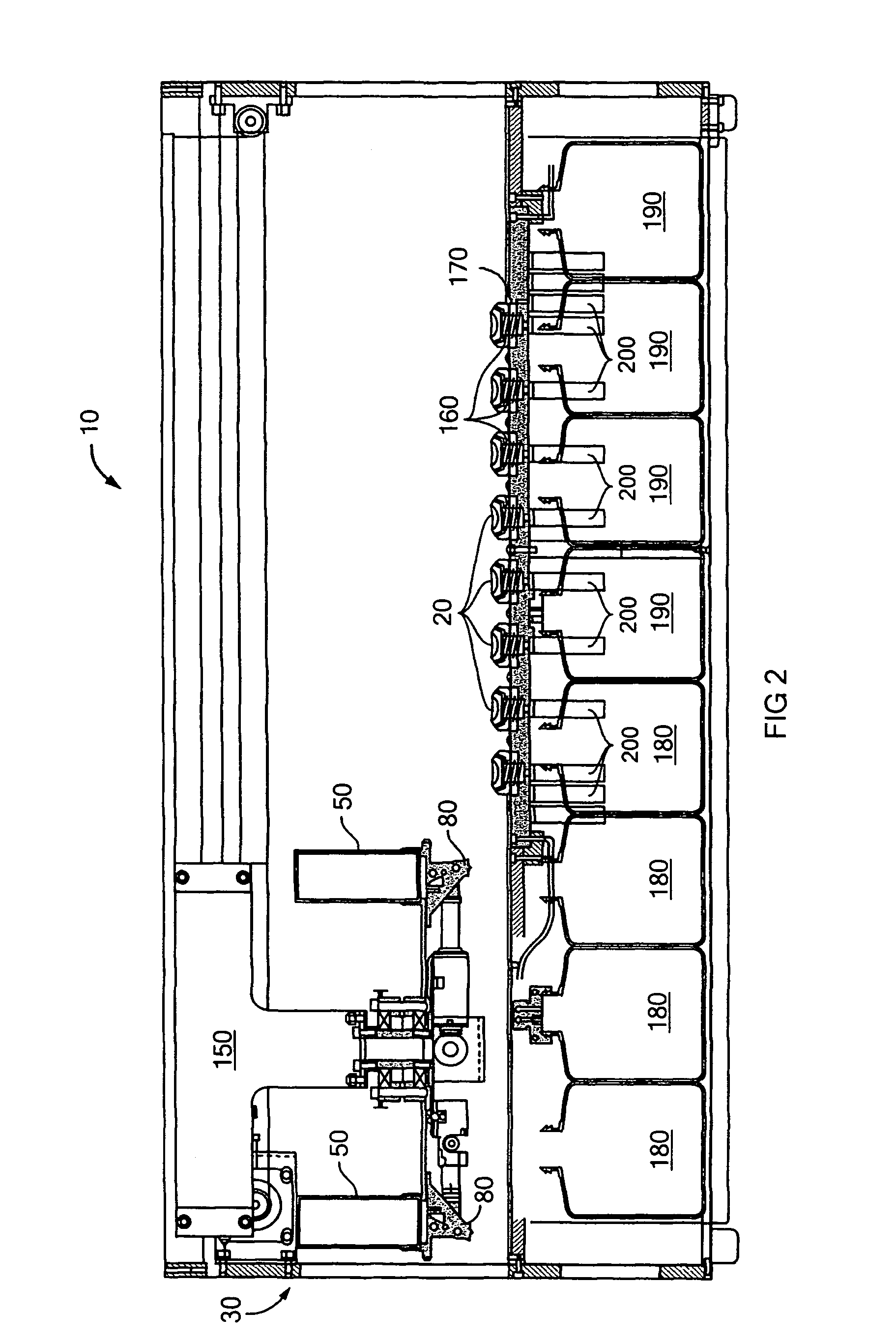
[0033]Referring to FIGS. 1 and 2, a tissue processing system 10 suitable for use with one or more slide, or sample, retaining trays 20 will now be described. The system 10 includes a fluid dispensing apparatus 30 having a plurality of stations 40 at which fluid dispensing cartridges 50 may be mounted. A fluid dispensing apparatus including a multiplicity of fluid dispensing ca...


PUM

PropertyMeasurementUnit
pressureaaaaaaaaaa
gravityaaaaaaaaaa
corrosion resistantaaaaaaaaaa

Abstract

A manifold assembly that directs fluid to and from individually selectable sample receiving trays of a tissue processing system includes a manifold, fluid conduits machined in the manifold, and valves that may be selectively configured to provide a direct fluid path to or from a particular tray. The valves are controlled by a controller that positions each valve such that a desired path is created. Pressure is created in supply and / or drain bottles to supply or drain fluid from the trays supported by the manifold assembly. Independently operated heaters are provided on the manifold assembly to heat the trays to desired temperatures. Thermoelectric cooling elements may also provided to cool the heaters and / or trays.

Description

[0001]This application is a continuation-in-part of co-pending U.S. patent application Ser. No. 10 / 639,021, filed on Aug. 11, 2003, and entitled “Fluid Dispensing Apparatus”, and claims priority to provisional U.S. patent application Ser. No. 60 / 652,440, entitled “Manifold Assembly”, filed on Feb. 11, 2005, both of which hereby are incorporated herein by reference in their entireties.FIELD OF THE INVENTION[0002]The present invention is directed to an automated tissue processing system and in particular, to a manifold assembly for a tissue processing system.BACKGROUND OF THE INVENTION[0003]Tissue processors can be operated with varying levels of automation to process human or animal tissue specimens for histology or pathology uses. Various types of chemical reagents can be used at various stages of tissue processing and various systems have been developed for delivering reagents to specimen containing slides. Examples of known reagent delivery systems include small quantity release d...

Claims


Application Information

Patent Timeline
Patent Type & Authority Patents(United States)
IPC IPC(8): G01N15/06B67D7/78
CPCG01N1/312G01N35/1097B01L9/52G01N1/18Y10T436/2575Y10T436/25Y10T436/25125
Inventor BUI, XUAN S.
Owner SAKURA FINETEK U S A
Why Eureka
Try Eureka