Power supply device and recording apparatus

a power supply device and recording device technology, applied in the direction of electric variable regulation, process and machine control, instruments, etc., can solve the problems of increasing the size of the resistor, increasing the limiting electric power, and not always constant applied voltage, etc., to achieve simple and inexpensive configuration

Inactive Publication Date: 2010-06-29
CANON KK
View PDF5 Cites 27 Cited by
  • Summary
  • Abstract
  • Description
  • Claims
  • Application Information

AI Technical Summary

Benefits of technology

[0066]The present invention is directed to a power supply device with a simple and inexpensive configuration that is capable of controlling an output according to an externally input control signal as required.

Problems solved by technology

However, the applied voltage is not always constant because of the DC-DC converter configured to modulate the output voltage.
In the typical resistor, as the electric power application time becomes longer, the limiting electric power decreases more.
Also, as the rated power becomes higher, the resistor size becomes larger and the limiting value of the pulse limiting electric power curve becomes high.
However, if the resistor size becomes larger, there is required a larger installation space, thus resulting in higher cost.
However, the electric power to be applied to the resistor becomes larger.
Therefore, the use of such a resistor having both a large rated power and a large resistor size is required.
However, in using the resistor within the pulse limiting electric power curve, a resistor having a large rated power and a large resistor size is required.
Also, in using a resistor requiring a small installation space, the electric power to be applied to the resistor is required to be limited within the pulse limiting electric power curve, such that the time period for stepping down the output voltage to the target value tends to take time in a conventional configuration.
Thus, a problem of increased cost arises.

Method used


Image

  • Power supply device and recording apparatus
  • Power supply device and recording apparatus
  • Power supply device and recording apparatus

Examples


first exemplary embodiment

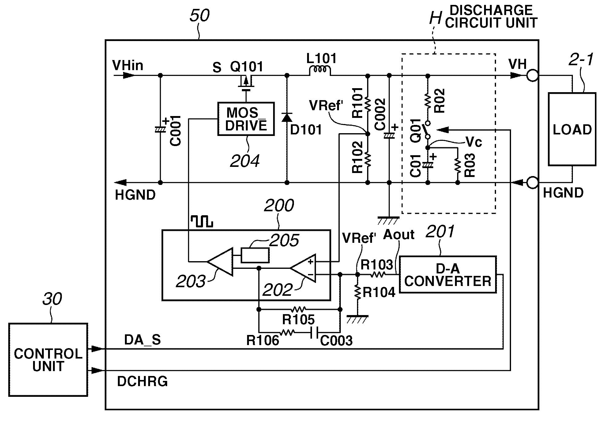
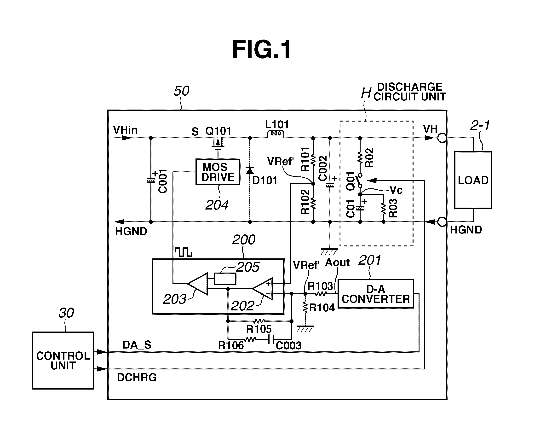
[0085]FIGS. 6 and 7 illustrate an example configuration of a recording apparatus with a power supply device (DC-DC converter) according to an exemplary embodiment of the invention.

[0086]The recording apparatus is of an inkjet recording type. As illustrated in FIG. 6, the recording apparatus includes an inkjet recording head unit configured to discharge ink. The inkjet recording head unit includes a recording head 2-1 for black (Bk) ink, a recording head 2-2 for yellow (Y) ink, a recording head 2-3 for magenta (M) ink, and a recording head 2-4 for cyan (C) ink. The recording heads 2-1 to 2-4 are configured integrally with ink tanks 1-1 to 1-4, respectively.

[0087]The recording heads 2-1 to 2-4 and ink tanks 1-1 to 1-4 are mounted on a head carriage 3 together with an optical home position sensor (hereinafter referred to as an “HP sensor”8 illustrated in FIG. 7) and a DC-DC converter 50 (FIG. 7).

[0088]The head carriage 3 is coupled to a portion of a driving belt 4, which transmits a dr...


PUM


Abstract

A power supply device includes a DC-DC converter configured to regulate an output voltage based on an externally input instruction, and a discharge circuit connected to an output capacitor of the DC-DC converter, wherein the discharge circuit includes a switch element configured to switch between a conductive state and a nonconductive state according to an instruction, and a capacitor-resistor (C-R) circuit configured to charge electric charge accumulated in the output capacitor of the DC-DC converter when the switch element is conductive and to discharge the electric charge to ground when the switch element is nonconductive.

Description

BACKGROUND OF THE INVENTION[0001]1. Field of the Invention[0002]The present invention relates to a power supply device with a DC-DC converter and a recording apparatus using the power supply device.[0003]2. Description of the Related Art[0004]A step-down DC-DC converter of pulse width modulation (PWM) switching type is used for power supply to a load of a drive source or an electric circuit in electronic apparatuses. The step-down DC-DC converter of PWM switching type generates a predetermined constant output voltage by performing constant value control while comparing a target voltage value for setting an output voltage with a feedback voltage value from the output voltage.[0005]A DC-DC converter that controls an output voltage to be supplied to a load controls the output voltage by changing a target voltage value for feedback constant voltage control according to a signal from an external control unit or an external electronic apparatus. Alternatively, the DC-DC converter changes ...

Claims


Application Information

Patent Timeline
Patent Type & Authority Patents(United States)
IPC IPC(8): G05F1/46G05F1/56
CPCH02M3/158H02M2001/322H02M1/322
Inventor SATO, TAKASHI
Owner CANON KK
Why Eureka
Try Eureka