Heat dissipation device with heat pipes

a heat dissipation device and heat pipe technology, which is applied in the direction of insulated conductors, cables, instruments, etc., can solve the problems of increasing heat generation, heat dissipation devices are no longer able to efficiently remove heat from these cpus, and heat is often produced, so as to improve the heat dissipation capacity of the heat dissipation device of the present invention and dissipate heat

Active Publication Date: 2010-06-29
CHAMP TECH OPTICAL FOSHAN
View PDF5 Cites 7 Cited by
  • Summary
  • Abstract
  • Description
  • Claims
  • Application Information

AI Technical Summary

Benefits of technology

[0008]A heat dissipation device in accordance with a preferred embodiment of the present invention is used for dissipating heat generated by an electronic device. The heat dissipation device comprises a base for contacting the electronic device. A fin set is located on the base for dissipating heat in the base to ambient air. A first heat pipe thermally engaged with the base for absorbing heat from the electronic device and spreading the heat to the base. The first heat pipe comprises a first transferring portion and two second transferring portions extending from two opposite free ends of the first transferring portion in opposite extension directions. A second heat pipe is thermally engaged with the base for absorbing heat from the electronic device and spreading the heat to the base. The second heat pipe has a first transferring section and a second transferring section extending from a free end of the first transferring section and parallel to the first transferring section. The first transferring section of the second heat pipe is located adjacent to the first transferring portion of the first heat pipe and the second transferring section of the second heat pipe is located adjacent to one of the second transferring portions of the first heat pipe. The first and second heat pipes cover most of a face of the base and spread the heat from the electronic device to all parts of the base rapidly. Therefore, the heat generated by the electronic device is evenly distributed to the base and heat dissipation capacity of the heat dissipation device of the present invention is improved greatly.

Problems solved by technology

During operation of an electronic device such as a computer central processing unit (CPU) mounted on a printed circuit board, a large amount of heat is often produced.
However, as electronics technology continues to advance, increasing amounts of heat are being generated by powerful state-of-the-art CPUs.
As a result, many conventional heat dissipation devices are no longer able to efficiently remove heat from these CPUs.
However, the heat pipe is straight, which results in a thermal contact area between the base and the heat pipe is considerably small.
Consequently, the heat in the center of the base cannot be transmitted to other parts of the base rapidly and evenly.
Normal functions and abilities of the electronic device are adversely affected.

Method used


Image

  • Heat dissipation device with heat pipes
  • Heat dissipation device with heat pipes
  • Heat dissipation device with heat pipes

Examples


Embodiment Construction

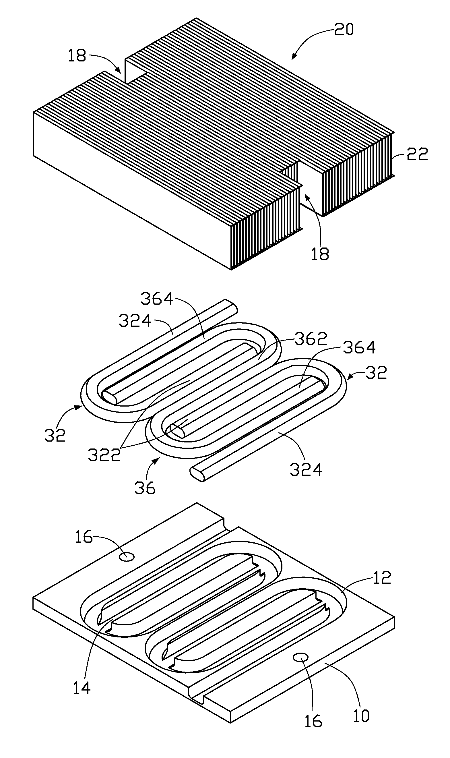
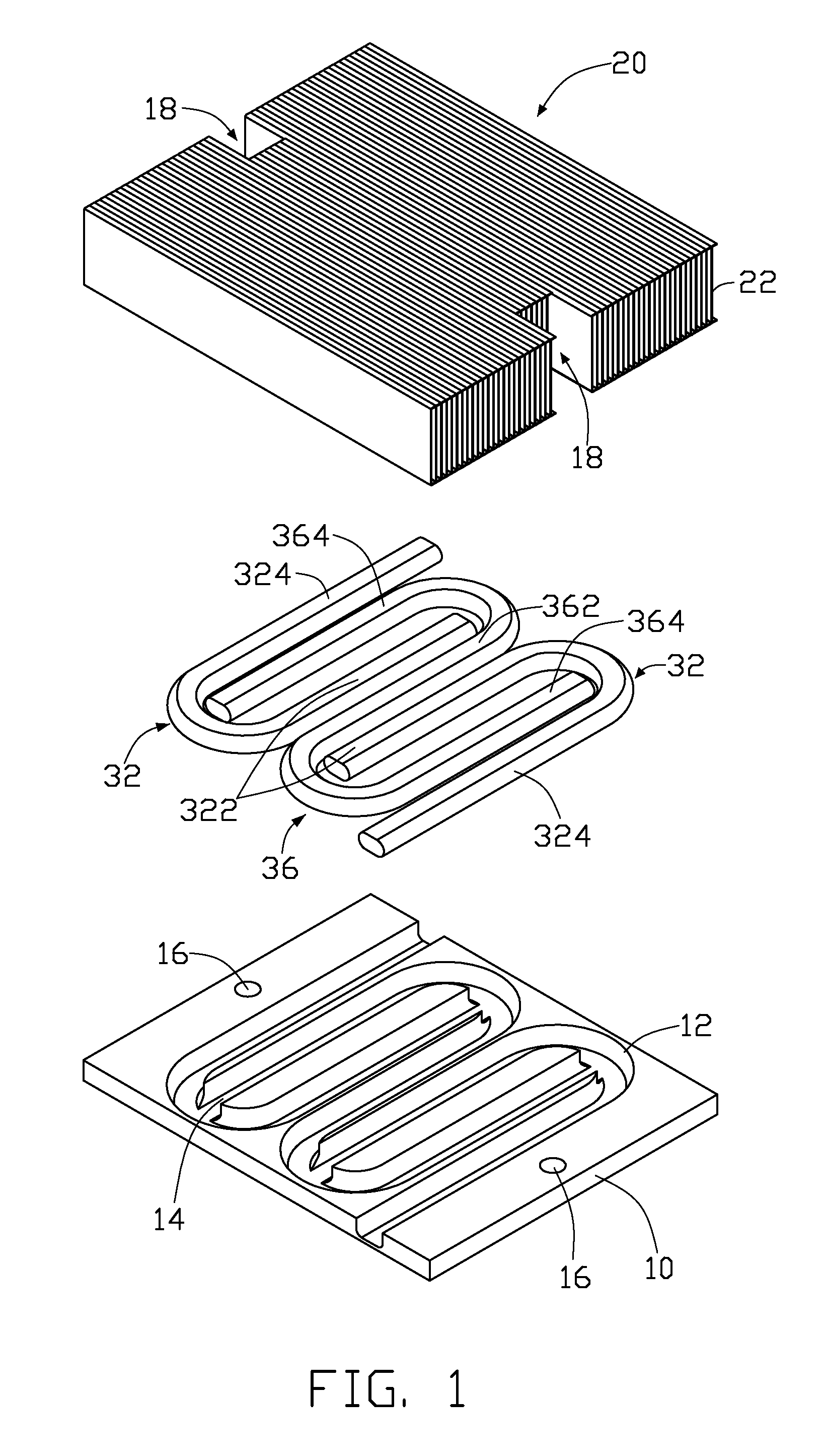
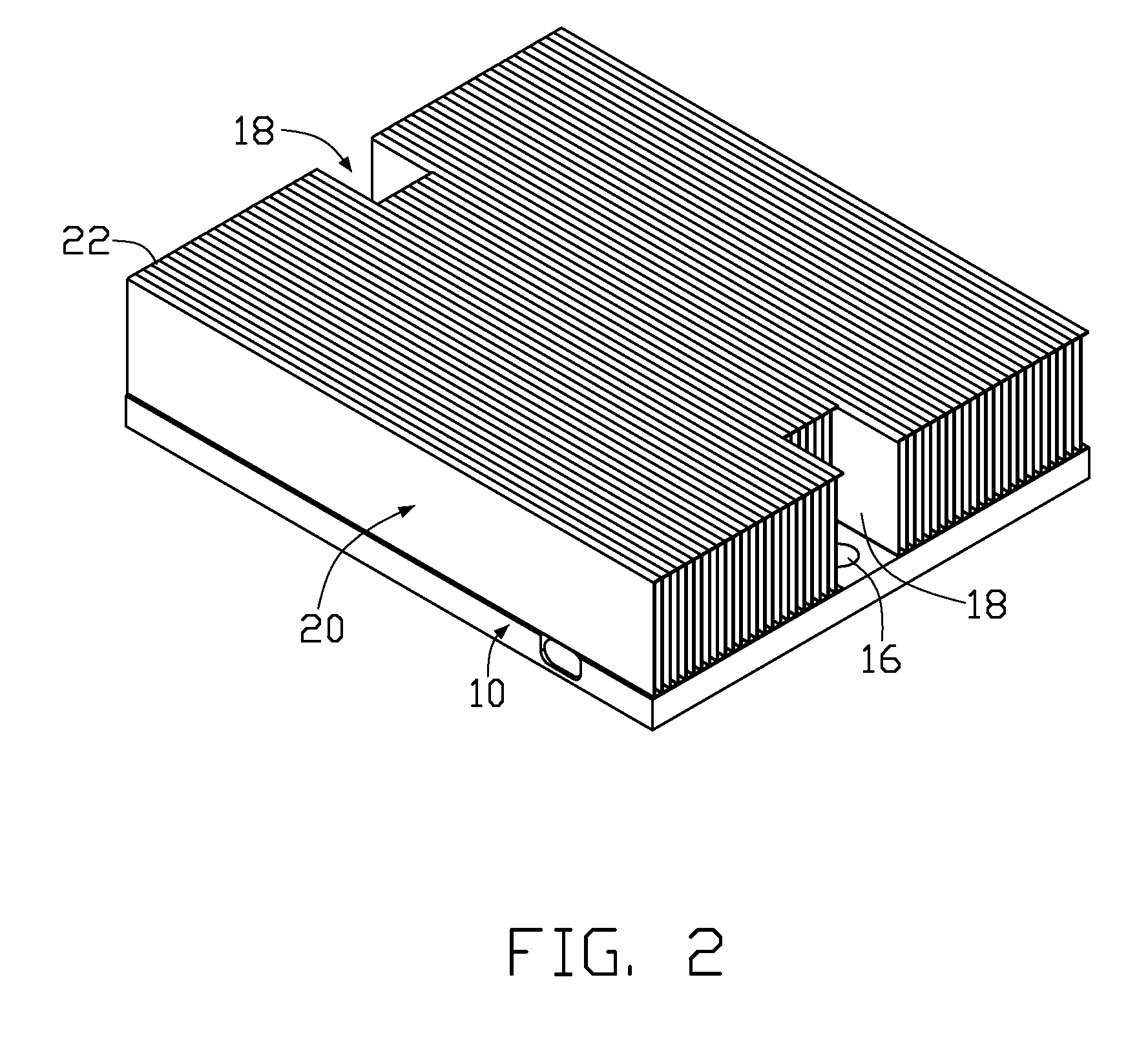
[0015]Referring to FIGS. 1-2, a heat dissipation device in accordance with a first embodiment of the present invention is used for dissipating heat generated by an electronic device (not shown) located on a printed circuit board (not shown). The heat dissipation device comprises a base 10, a fin set 20 for being soldered on and thermally contacting with the base 10, and a first heat pipe 36 and two second heat pipes 32 for being embedded in the base 10 and thermally connecting with the base 10 and the fin set 20.

[0016]The base 10 is a substantially rectangular metal plate having good heat conductivity, and has a bottom face (not shown) for contacting the electronic device and a top face (not labeled) opposite to the bottom face. A first groove 14 and a pair of second grooves 12 are defined in the top face of the base 10, for receiving corresponding the first and second heat pipes 36, 32 therein. The first groove 14 is substantially S-shaped and defined in a center portion of the top...


PUM


Abstract

A heat dissipation device includes a base for contacting an electronic device, a fin set located on the base and first, second heat pipes thermally engaged in the base. The first heat pipe comprises a first transferring portion and two second transferring portions extending from two opposite free ends of the first transferring portion. The second heat pipe has first and second transferring sections. The first transferring section of the second heat pipe is located adjacent to the first transferring portion of the first heat pipe and between the first transferring portion and one of the second transferring portions of the first heat pipe, and the second transferring section of the second heat pipe is located adjacent to the one of the second transferring portions of the first heat pipe.

Description

BACKGROUND OF THE INVENTION[0001]1. Field of the Invention[0002]The present invention relates to heat dissipation devices for use in removing heat from electronic devices, and more particularly to a heat dissipation device incorporating heat pipes for improving heat dissipation efficiency of the heat dissipation device.[0003]2. Description of Related Art[0004]During operation of an electronic device such as a computer central processing unit (CPU) mounted on a printed circuit board, a large amount of heat is often produced. The heat must be quickly removed from the CPU to prevent it from becoming unstable or being damaged. Typically, a heat dissipation device is attached to an outer surface of the CPU to absorb heat from the CPU. The heat absorbed by the heat dissipation device is then dissipated to ambient air.[0005]Conventionally, a heat dissipation device comprises a solid metal base attached on the CPU, and a plurality of fins arranged on the base. The base is intimately attache...

Claims


Application Information

Patent Timeline
Patent Type & Authority Patents(United States)
IPC IPC(8): H05K7/20H01L23/34F28F7/00
CPCF28D15/0233F28D15/0275G06F1/20H01L23/427H01L2924/0002H01L2924/00
Inventor CAO, LEIZHENG, DONG-BOFU, MENGCHEN, CHUN-CHI
Owner CHAMP TECH OPTICAL FOSHAN
Why Eureka
Try Eureka