Bearing system and balancer

a bearing system and balancer technology, applied in the direction of crankshafts, sliding contact bearings, machines/engines, etc., can solve the problems of seizing, slide bearing life decline, and slide bearing failure, so as to reduce the load on the bearing member, increase the life of the bearing member, and reduce the speed of the bearing member relative to the component rotating in the opposite direction

Active Publication Date: 2010-07-06
YAMAHA MOTOR CO LTD
View PDF6 Cites 7 Cited by
  • Summary
  • Abstract
  • Description
  • Claims
  • Application Information

AI Technical Summary

Benefits of technology

[0010]The present invention relates to a structure that reduces a load to a bearing member interposed between the balance weight and the shaft.
[0011]Accordingly, it is an object of the invention to provide a bearing system that can reduce the relative velocity between a bearing member and a rotation shaft and a rotating member to decrease a load on the bearing member although the rotation shaft and the rotating member rotate in opposite directions with the bearing member therebetween.
[0012]It is another object of the invention to provide a balancer that can reduce the relative velocity between the bearing member and a crankshaft and a balance weight to decrease the load on the bearing member although the crankshaft and the balance weight rotate in opposite directions with the bearing member therebetween.
[0015]According to an aspect of the present invention, the velocity of a bearing member relative to a component rotating in the opposite direction can be decreased because the bearing member is separated from the component. Therefore, the load on the bearing member can be reduced so that the life of the bearing member can be increased and the occurrence of extraordinary wear that may cause seizing or the like can be prevented.

Problems solved by technology

This poses disadvantages of decreasing the life of the slide bearing and generating extraordinary wear, which may cause seizing, in the slide bearing.

Method used


Image

  • Bearing system and balancer
  • Bearing system and balancer
  • Bearing system and balancer

Examples


first embodiment

[0025]the invention will be described below with reference to FIGS. 1 to 6.

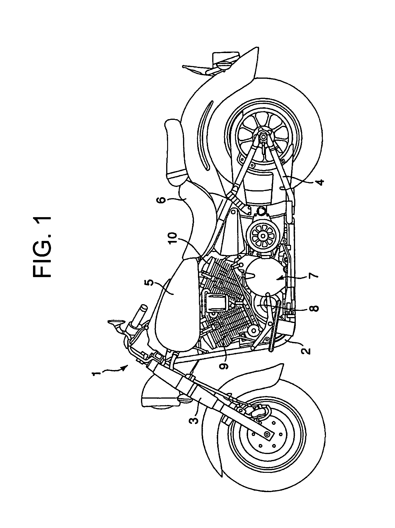
[0026]FIG. 1 discloses a vehicle, such as a motorcycle 1, according to one embodiment of the present invention. The motorcycle 1 includes a frame 2 shaped like a cradle. The frame 2 supports a front fork 3, a rear swing arm 4, a fuel tank 5, and a seat 6.

[0027]The frame 2 supports, for example, an air-cooled four-cycle V-2 engine 7. The engine 7 is disposed behind the front fork 3 and below the fuel tank 5.

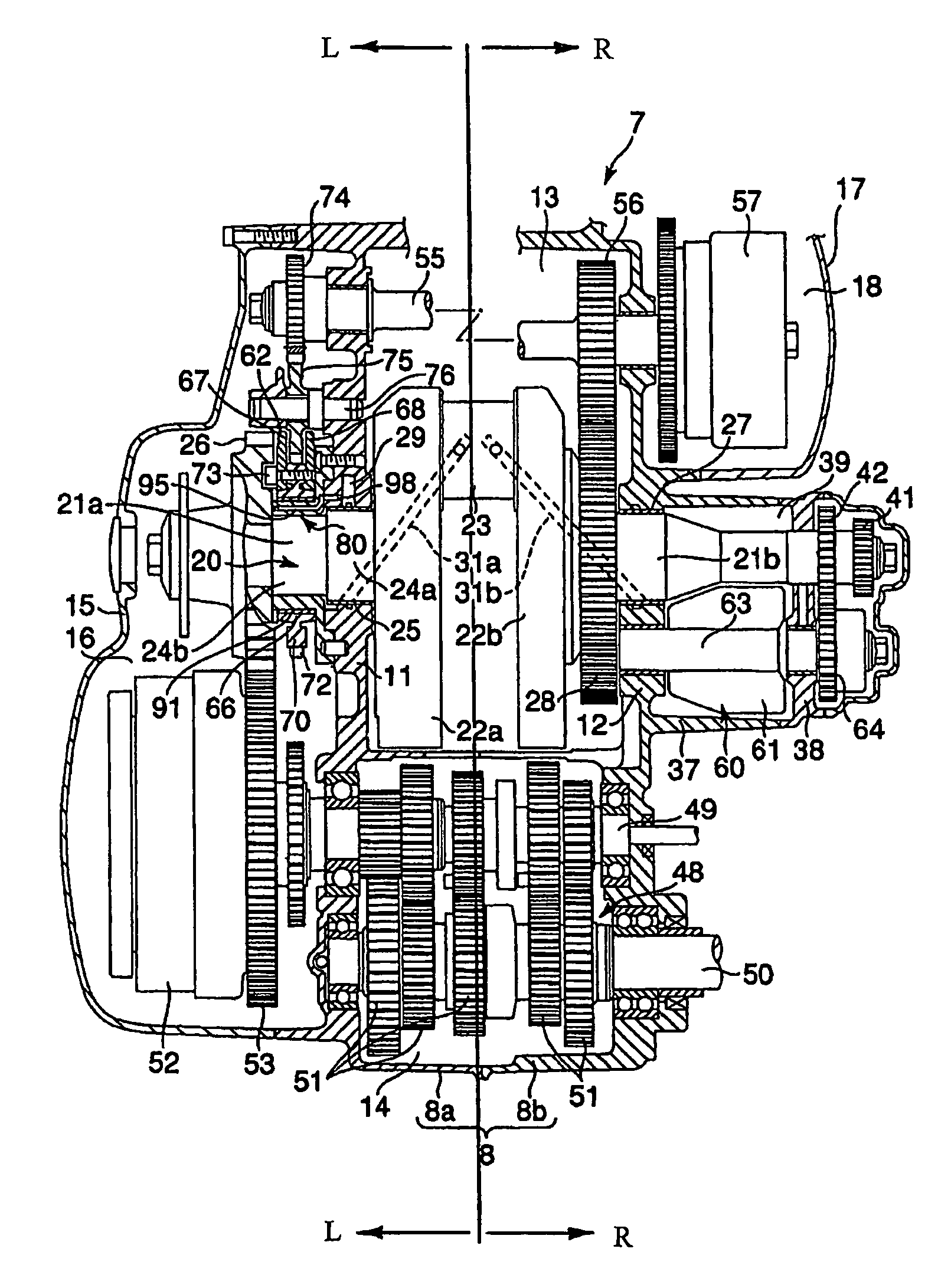
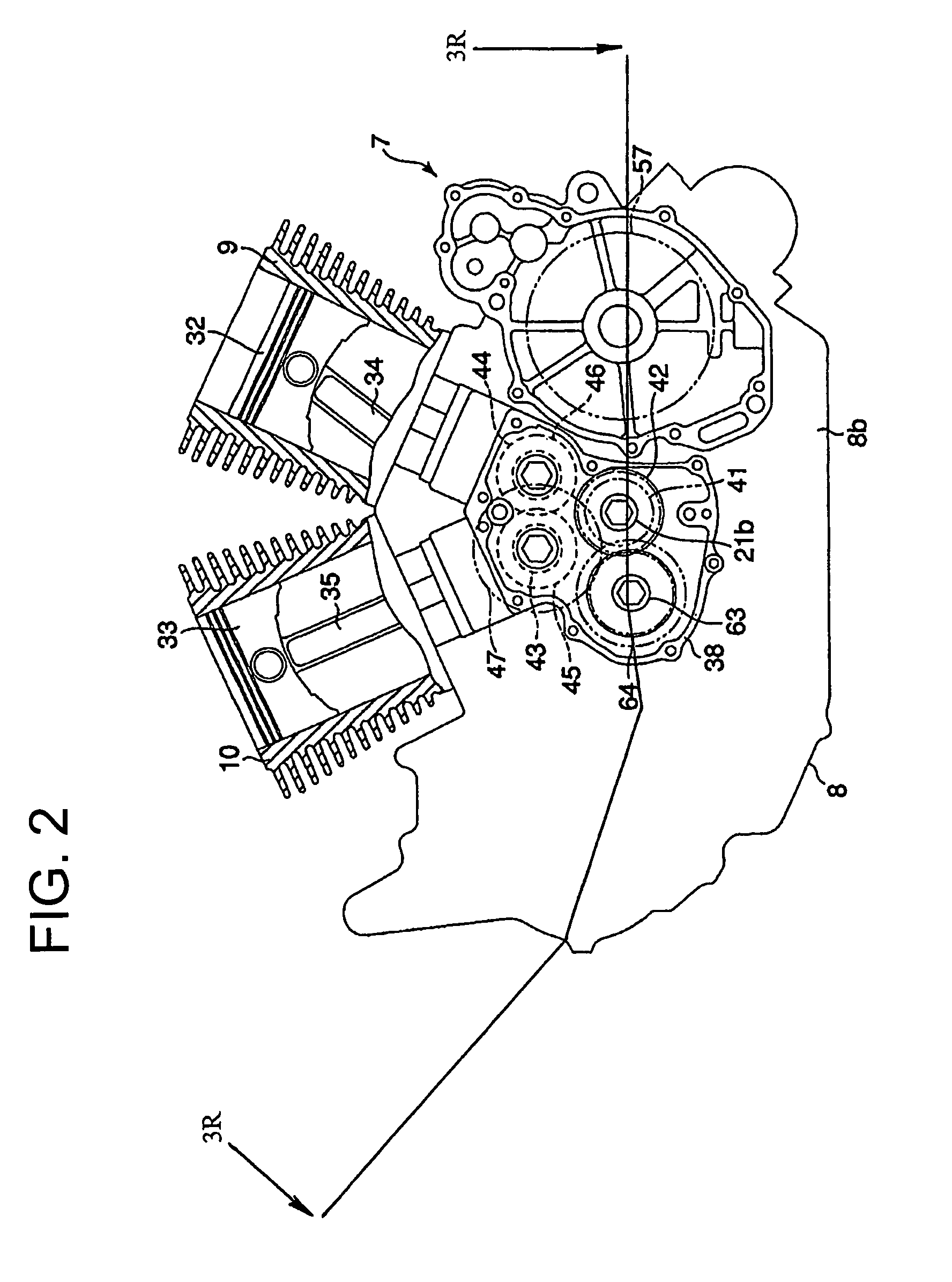
[0028]The engine 7 includes a crankcase 8, a front cylinder 9, and a rear cylinder 10. As shown in FIG. 3, the crankcase 8 is divided into a left case 8a and a right case 8b. The left case 8a has a support wall 11. The right case 8b has a support wall 12. The support walls 11 and 12 extend along the length of the crankcase 8 and are opposed to each other along the width of the crankcase 8 with a space therebetween. Between the left case 8a and the right case 8b, a crank chamber 13 and a transmission chamber...

second embodiment

[0080]According to the invention, lubricating oil can be supplied from the crankshaft 20 to the slide bearing 91. Therefore, there is no need to have a complicated passage in the housing 80 or the support wall 11 for distributing the lubricating oil flowing in the feed passage 29 to the slide bearing 91. This can simplify the structure of the housing 80, thereby reducing the manufacturing cost for the housing 80.

third embodiment

[0081]FIGS. 8 and 9 disclose the invention.

[0082]The difference between the third embodiment and the second embodiment is the structure for rotatably supporting the second balance weight 62. The other structure is the same as that of the second embodiment. Accordingly, the components of the third embodiment the same as those of the second components are given the same reference numerals and their description will be omitted.

[0083]As shown in FIG. 8, the second portion 24b of the shaft 21a passes through the boss 66 of the second balance weight 62 coaxially. The slide bearing 91 is interposed between the outer circumference of the second portion 24b and the inner circumference of the bearing hole 69 of the boss 66. The slide bearing 91 is fitted to the outer circumference of the second portion 24b and the inner circumference of the bearing hole 69 with clearance therebetween, respectively.

[0084]Accordingly, as shown in FIG. 9, the slide bearing 91 defines a clearance 114 between it a...


PUM

PropertyMeasurementUnit
radiusaaaaaaaaaa
weightaaaaaaaaaa
weightsaaaaaaaaaa

Abstract

A bearing system can reduce the relative velocity between a bearing member and a rotation shaft and a rotating member to decrease a load on the bearing member although the rotation shaft and the rotating member rotate in opposite directions with the bearing member therebetween. The bearing system includes a case and a rotation shaft supported by the case. A rotating member is disposed coaxially outside the rotation shaft and rotates in the direction opposite to that of the rotation shaft. A housing is interposed between the rotation shaft and the rotating member and is fixed to the case. A bearing member that rotatably supports the rotating member is interposed between the housing and the rotating member.

Description

BACKGROUND OF THE INVENTION[0001]1. Field of the Invention[0002]The present invention relates to a bearing system and balancer.[0003]2. Description of Related Art[0004]Conventional engines for vehicles, such as motorcycle engines, have a balancer for reducing the vibration of the engines housed in the crankcase.[0005]In general, the balancer is used to cancel an inertial force generated by a reciprocating component represented by a piston and a con'rod. The balancer has a balance weight that rotates in the direction opposite to that of the crankshaft at the same speed. The balance weight is disposed coaxially on the shaft of the crankshaft or on a shaft different from the crankshaft. In either case, the balance weight is driven by the power transmitted from the crankshaft.[0006]The balance weight disposed coaxially with the crankshaft has a boss through which the shaft of the crankshaft passes. The boss is supported rotatably around the outer circumference of the shaft via a slide b...

Claims


Application Information

Patent Timeline
Patent Type & Authority Patents(United States)
IPC IPC(8): F16C3/04F16C33/10F16C11/00F02B75/06F16N1/00F01M1/06F02B77/00F16C3/14F16C3/18F16C3/20F16C9/02F16C17/02F16F15/26F16H57/021F16H57/028F16H57/029F16H57/03
CPCF16F15/267Y10T74/2173Y10T74/2183Y10T74/2174Y10T29/49249
Inventor TAKEUCHI, YOSHIHIKO
Owner YAMAHA MOTOR CO LTD
Why Eureka
Try Eureka