Gas diverter for an electrical switching device

Active Publication Date: 2010-07-06
ROCKWELL AUTOMATION TECH
View PDF5 Cites 4 Cited by
  • Summary
  • Abstract
  • Description
  • Claims
  • Application Information

AI Technical Summary

Benefits of technology

[0006]The present invention provides an improved gas handling arrangement designed to respond to such needs. The invention provides an innovative approach for slowing, cooling, and diverting high temperature gas and plasma generated by switching devices. The invention provides a gas diverter that mounts to the switching device and has an inlet for accepting gas and exit for expelling the gas. The gas diverter further has peripheral walls and internal partitions that provide a circuitous flow path that slows, cools, and diverts the gas before release. In

Problems solved by technology

Concerns in such situations include potential phase-to-phase short circuits in multi-phase devices, and the release of hot gases.
The ionized gas that may exit the devices is gener

Method used


Image

  • Gas diverter for an electrical switching device
  • Gas diverter for an electrical switching device
  • Gas diverter for an electrical switching device

Examples


Embodiment Construction

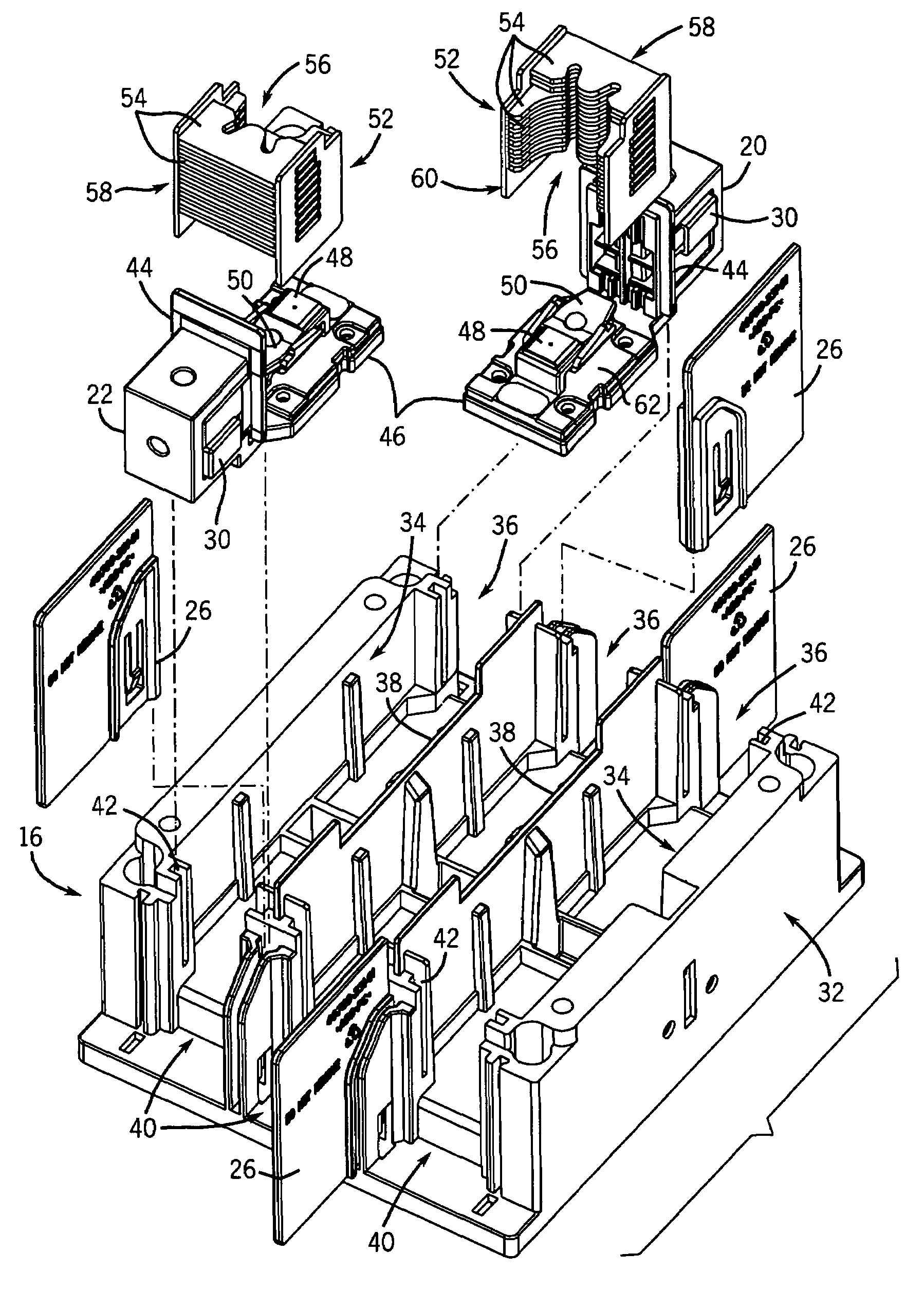
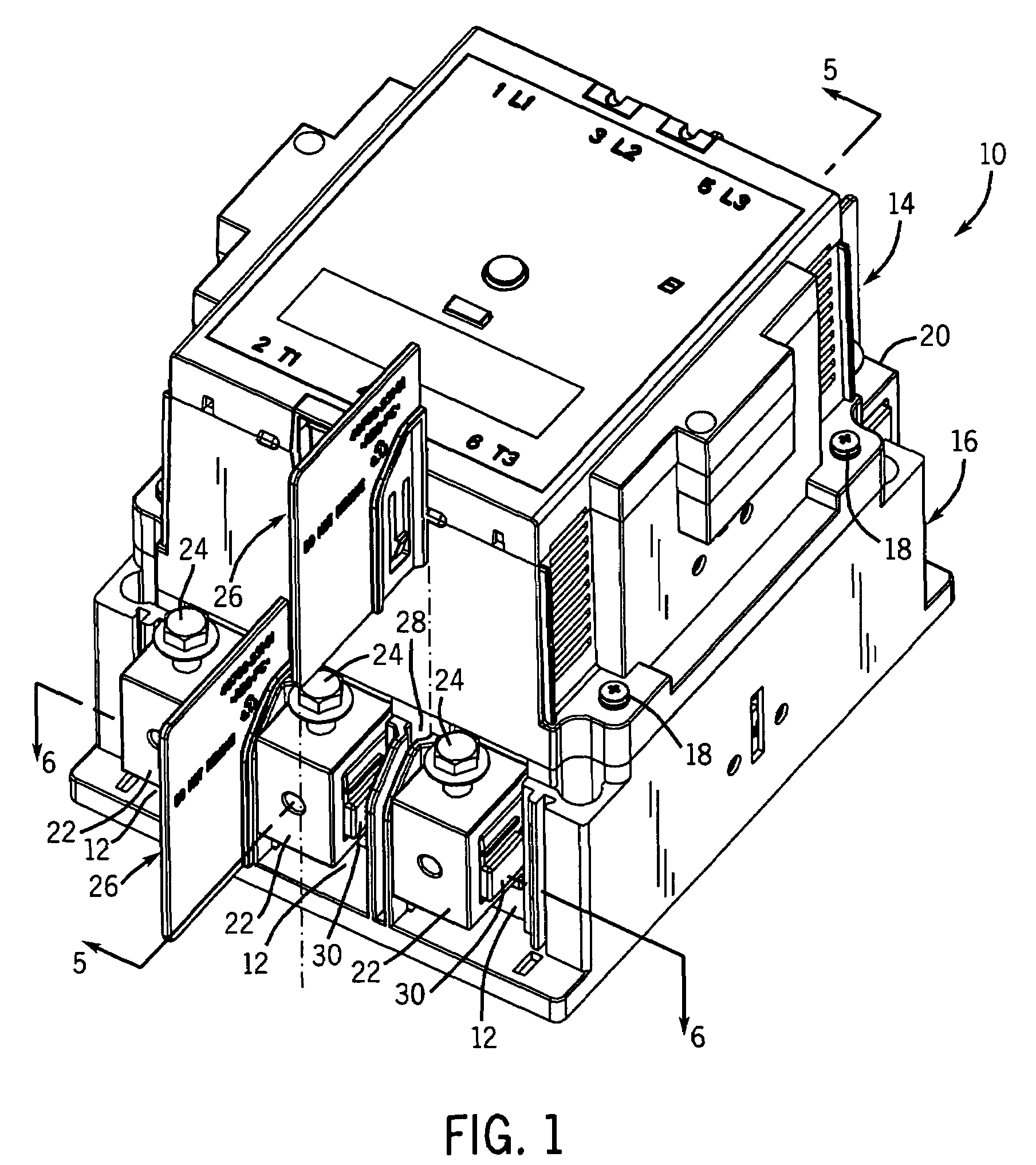
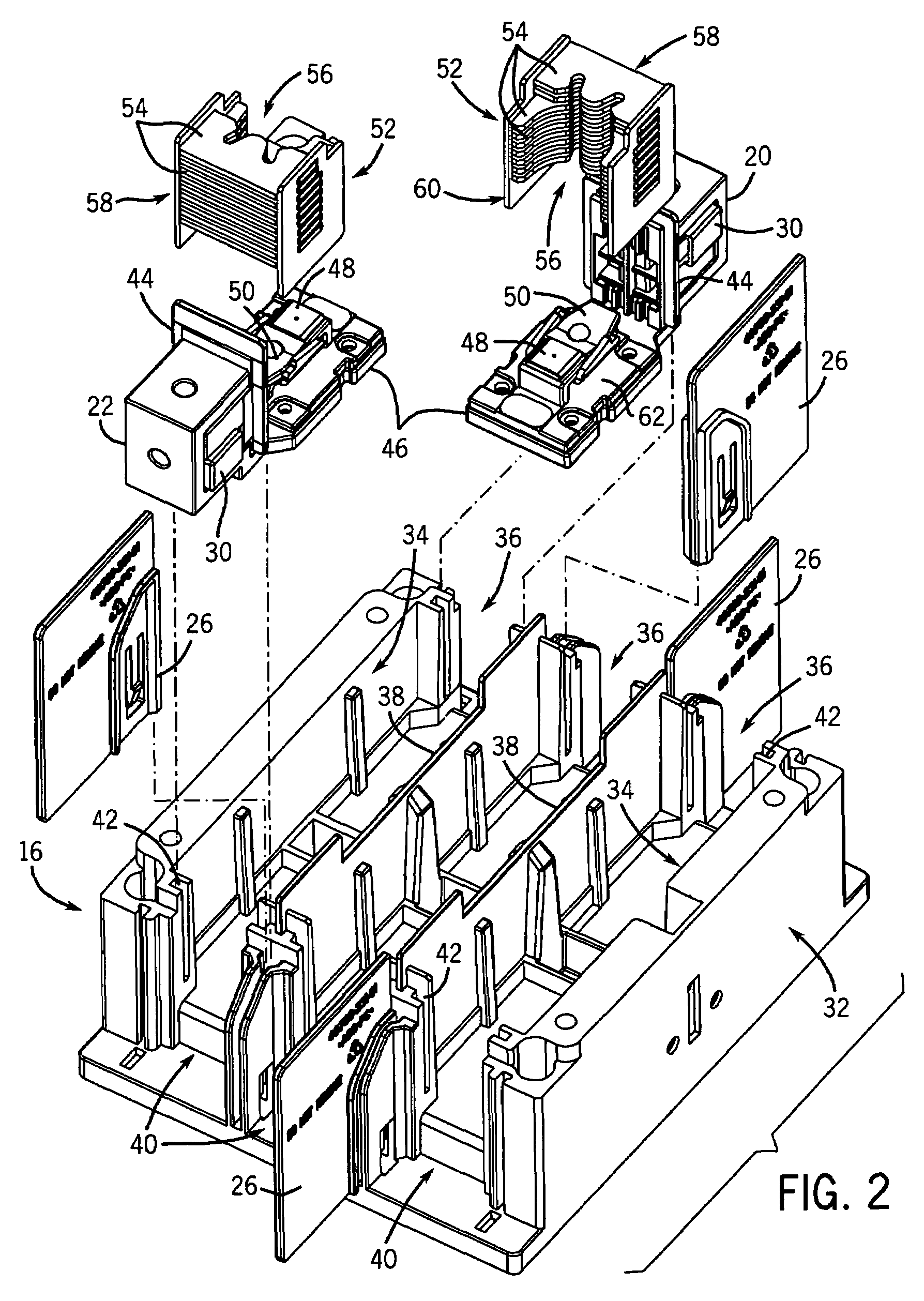
[0016]Turning now to the drawings, FIG. 1 illustrates an electrical switching device 10 in the form of a three-phase contactor for completing electrical current carrying paths for three separate phases 12 of electrical power. The switching device 10 includes an actuating section 14 and a contacting section 16 joined by fasteners 18. The actuating section contains the electromagnetic operator that mechanically opens and closes current carrying paths through the device. The operation and relevant internal components of the device will be discussed in more detail below. In general, however, each phase section 12 has an input or line terminal 20 and output or load terminal 22. Wire lugs 24 are secured to both the input and output terminals for receiving and completing an electrical connection with current-carrying wires or cables of a conventional design. Dividing panels or phase barriers 26 may be used to isolate vented gas from one phase from the neighboring phase. The phase barriers ...


PUM


Abstract

A gas diverter is disclosed that slows, cools, and directs the hot gas and plasma generated during the operation of an electrical switching device. The gas diverter mounts to the switching device and has an inlet for accepting the gas and exit for expelling the gas. The diverter has peripheral walls and internal partitions that divide the gas and provide for two independent circuitous flow paths. In multi-phase switching devices, a plurality of gas diverters may be used to further separate the gases generated in each respective phase. The gas diverter is made of a high temperature, arc resistant plastic which is molded to form a two piece structure. The gas diverter is mounted to the device via a slide in place flange-channel mechanism.

Description

BACKGROUND[0001]The present invention relates generally to the field of electrical contactors, circuit interrupters, circuit breakers, and similar devices. More particularly, the invention relates to a gas diverter used to slow, cool, and divert hot gas generated during the operation of electrical switching devices.[0002]A variety of electrical switching devices are known and commercially available for establishing and interrupting current carrying paths between an electrical energy source and an electrical load. Electromechanical switchgear, for instance, is known for both single-phase and multiple-phase circuits. Such equipment generally includes an actuating assembly mechanically connected to a switch or contactor structure. In remotely-controllable switchgear of this type, it is commonplace to provide an electromagnetic actuating assembly which operates either on alternating current or direct current. The actuating assembly is energized by a control signal, such as from a remote...

Claims


Application Information

Patent Timeline
IPC IPC(8): H01H9/30
CPCH01H9/342H01H1/58H01H9/0264
Inventor DUCHROW, ROBERT A.BUSH, PHILLIPMILLER, JAMES P.HOUCK, III, THEODORE JOHNBERRY, WILLIAM R.
Owner ROCKWELL AUTOMATION TECH
Why Eureka
Try Eureka