Image display device capable of shifting a data line destination

a technology of image display device and data line destination, which is applied in the field of image display device and image display apparatus, can solve the problems of difficult to attach image display device to prism with high precision, difficult to improve yield, and positional displacement of display device, so as to reduce the number of man-hours, simple circuit configuration, and easy to change the position of video display

Inactive Publication Date: 2010-07-06
SONY CORP
View PDF8 Cites 0 Cited by
  • Summary
  • Abstract
  • Description
  • Claims
  • Application Information

AI Technical Summary

Benefits of technology

[0015]Hence, according to the present invention, it is possible to change the position of video display easily without relying on a signal processing system. This eliminates the existing needs for exchange of signals between drivers and for an outermost driver, thus making it possible to reduce the number of man-hours and cost.

Problems solved by technology

In actuality, however, it is very difficult to attach image display devices to a prism with high precision.
In addition, a positional displacement of a display device may occur after the attachment.
It is thus difficult to improve yield.
In particular, it is difficult to correct a positional displacement after the attachment once the image display devices have been fixed, so that the positional displacement leads directly to a product defect.
However, this increases burdens in terms of circuitry and cost because of for example needs for exchange of signals between drivers necessary at a display position and for an additional driver for outermost display pixels.

Method used


Image

  • Image display device capable of shifting a data line destination
  • Image display device capable of shifting a data line destination
  • Image display device capable of shifting a data line destination

Examples


Embodiment Construction

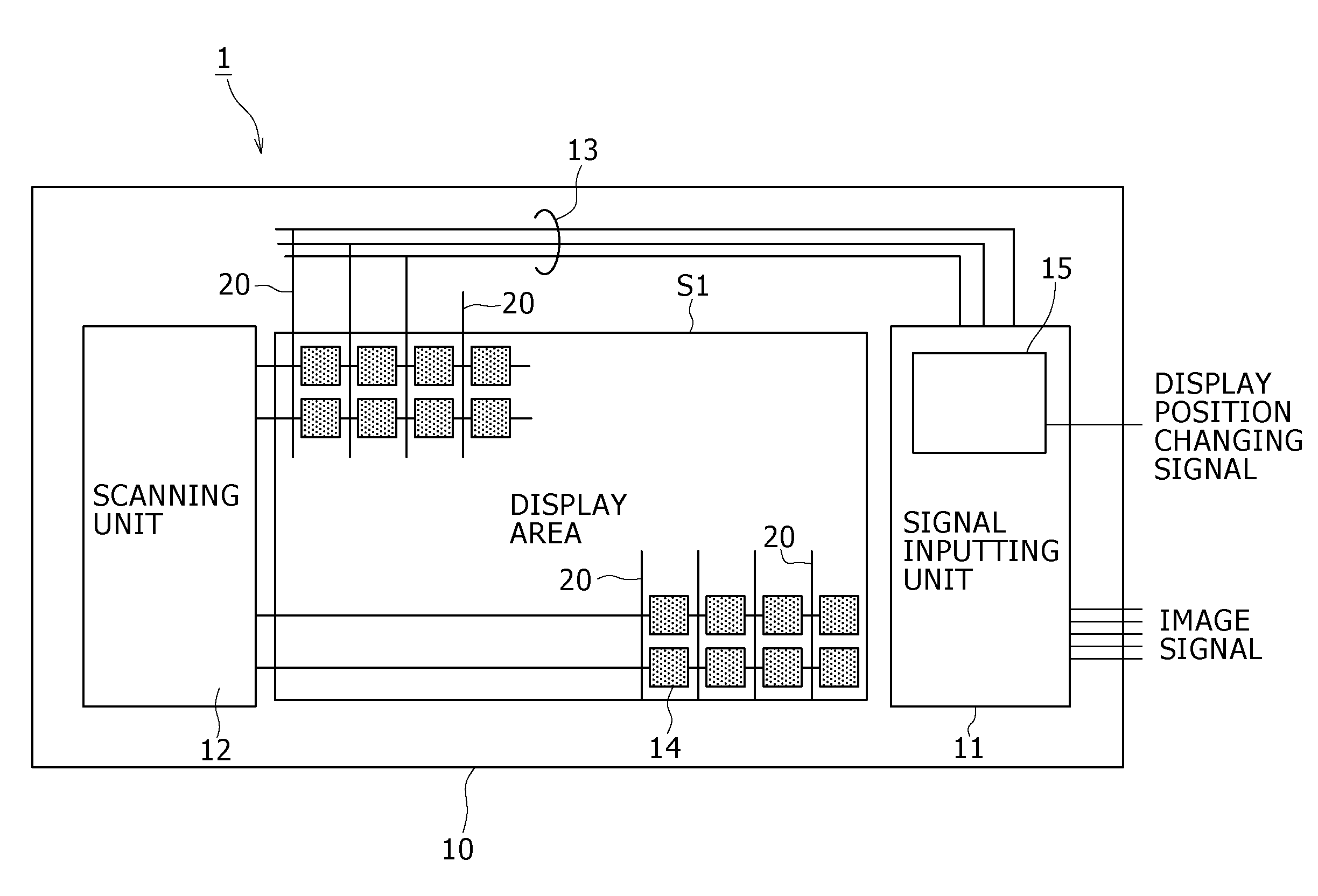
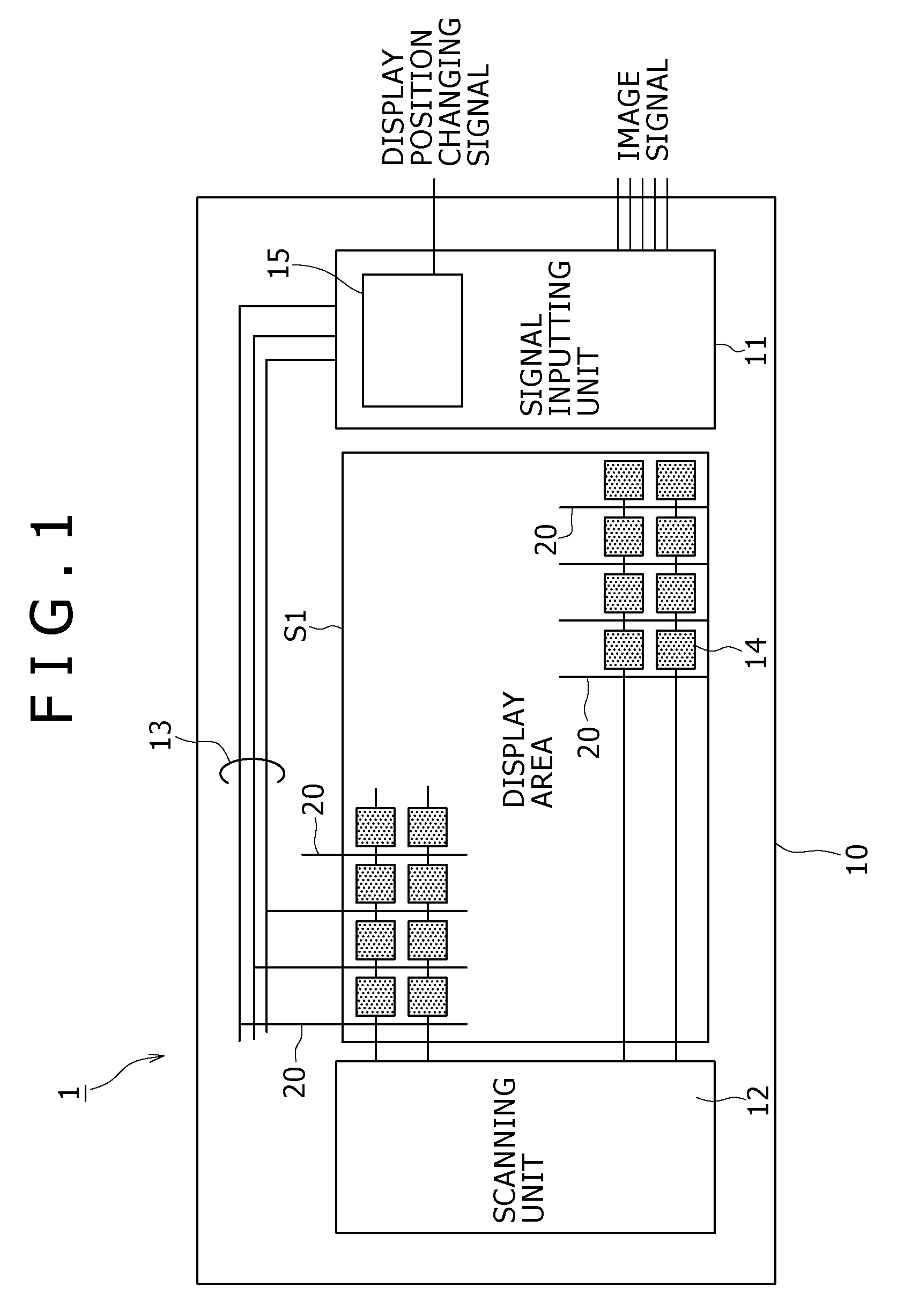
[0021]A preferred embodiment of the present invention will hereinafter be described with reference to the drawings. FIG. 1 is a schematic plan view of assistance in explaining a liquid crystal display device as an example of an image display device according to the present embodiment. The liquid crystal display device 1 is a reflective type liquid crystal device. The liquid crystal display device 1 includes: a pair of substrates, one of the substrates being superposed on the other with a predetermined gap therebetween, and the gap being filled with a liquid crystal; a plurality of pixels 14 (pixel group) provided in a region filled with the liquid crystal; a driver circuit (a signal inputting unit 11 and a scanning unit 12) for driving the plurality of pixels 14; and data buses 13 for supplying an image signal from the signal inputting unit 11 to each pixel column.

[0022]Since FIG. 1 is a schematic plan view, the driving side substrate 10 of the pair of substrates is shown. The refle...


PUM


Abstract

An image display device including: a pixel group formed by arranging a plurality of pixels; a driver circuit configured to supply an image signal to each pixel in the pixel group; and a switch circuit configured to shift a destination to which the image signal is supplied in a unit of a pixel pitch by circuit switching for bus lines for transmitting the image signal from the driver circuit to each pixel in the pixel group.

Description

CROSS REFERENCES TO RELATED APPLICATIONS[0001]The present invention contains subject matter related to Japanese Patent Application JP 2006-055691 filed in the Japanese Patent Office on Mar. 2, 2006, the entire contents of which being incorporated herein by reference.BACKGROUND OF THE INVENTION[0002]1. Field of the Invention[0003]The present invention relates to an image display device and an image display apparatus that display an image by a pixel group formed by a plurality of pixels.[0004]2. Description of the Related Art[0005]Projection type video display devices, for example, that display a picture using a plurality of image display devices employ a system referred to as a three-panel type system using three image display devices. This method separates light into three colors of red, green, and blue, changes the luminance of each of the colors by the image display devices, and thereafter synthesizes the results by an optical block such as a prism, whereby a desired picture is ob...

Claims


Application Information

Patent Timeline
Patent Type & Authority Patents(United States)
IPC IPC(8): G09G3/36
CPCG09G3/002G09G3/3688G09G2310/0297G09G3/20G09G3/34G09G3/36H04N5/74
Inventor KAWAURA, HIDEAKI
Owner SONY CORP
Why Eureka
Try Eureka