Camera calibration system and three-dimensional measuring system

a three-dimensional measuring and camera technology, applied in the field of three-dimensional measuring systems and cameras, can solve the problems of large equipment, inability to integrate information from multiple viewpoints, and inability to measure the shape of a portion of the object at the backside in relation to the camera

Inactive Publication Date: 2010-07-06
SPACEVISION
View PDF16 Cites 17 Cited by
  • Summary
  • Abstract
  • Description
  • Claims
  • Application Information

AI Technical Summary

Problems solved by technology

However, in all of these methods, the shape cannot be measured for a portion of the object which is at a backside in relation to the camera or for a portion of the object which is in a blind spot.
However, this method has a disadvantage in that the equipment becomes large-scaled.
However, the information from the multiple viewpoints cannot be integrated unless the positions and orientations of the moved camera are known.
Although the position and orientation of the camera at each image-capturing point can be easily determined by employing a mechanism to move the camera along a track, such a mechanism would increase the size of the device.
When the shape of the marker changes, the shape would differ from the shape of the marker registered in the calibration device, and, thus, the identification precision of the markers on the panel is lowered, resulting, in some cases, in inability to calibrate.
In addition, although another method is proposed in the related art in which the markers are determined not by shape but by color, the color of the markers on the panel would change due to conditions of the illumination light or the like, and, thus, there has been a problem in that the identification precision of the markers may be lowered depending on the illumination conditions.

Method used


Image

  • Camera calibration system and three-dimensional measuring system
  • Camera calibration system and three-dimensional measuring system
  • Camera calibration system and three-dimensional measuring system

Examples


Embodiment Construction

[0025]A preferred embodiment of the present invention will now be described by reference to the drawings.

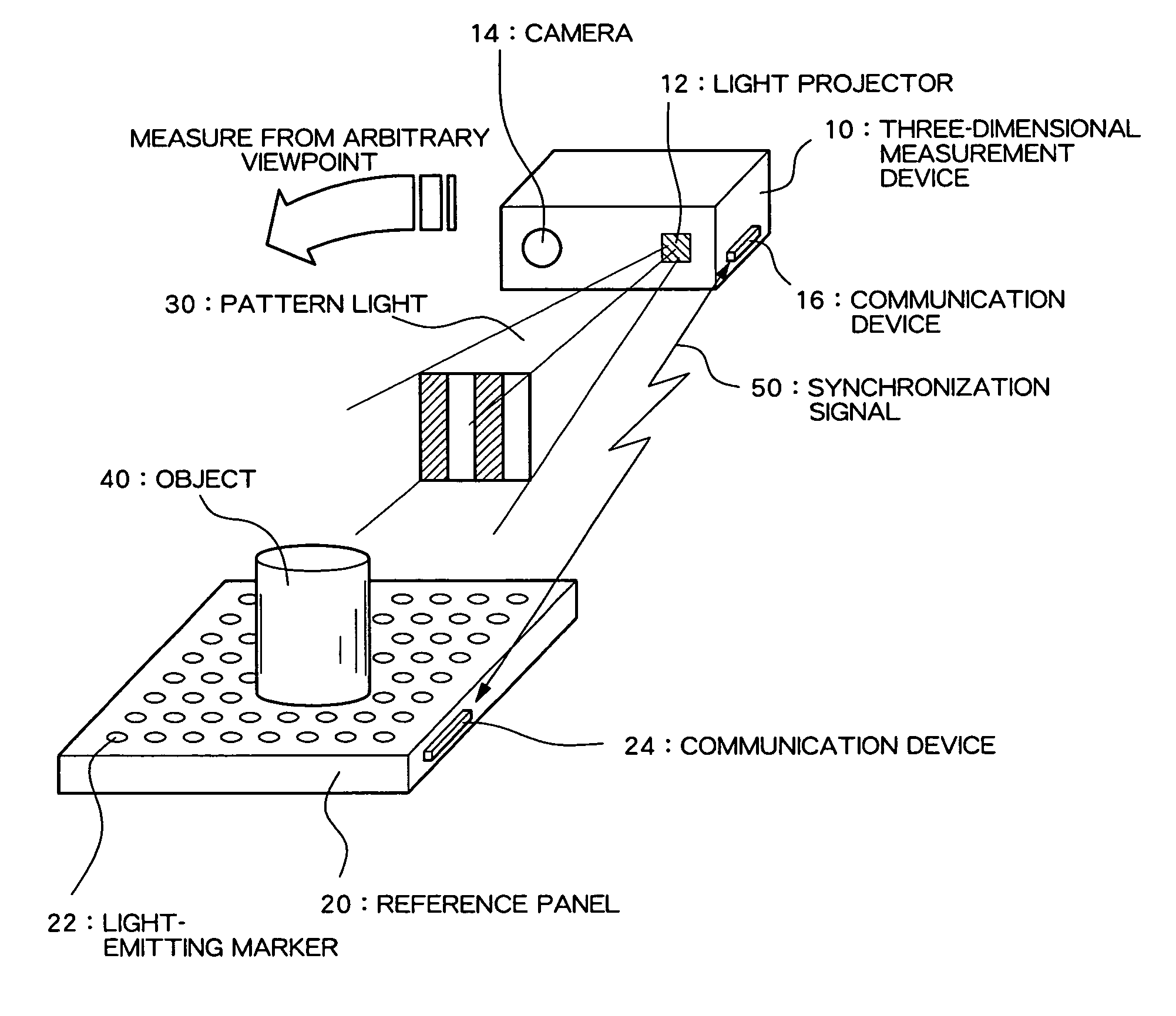
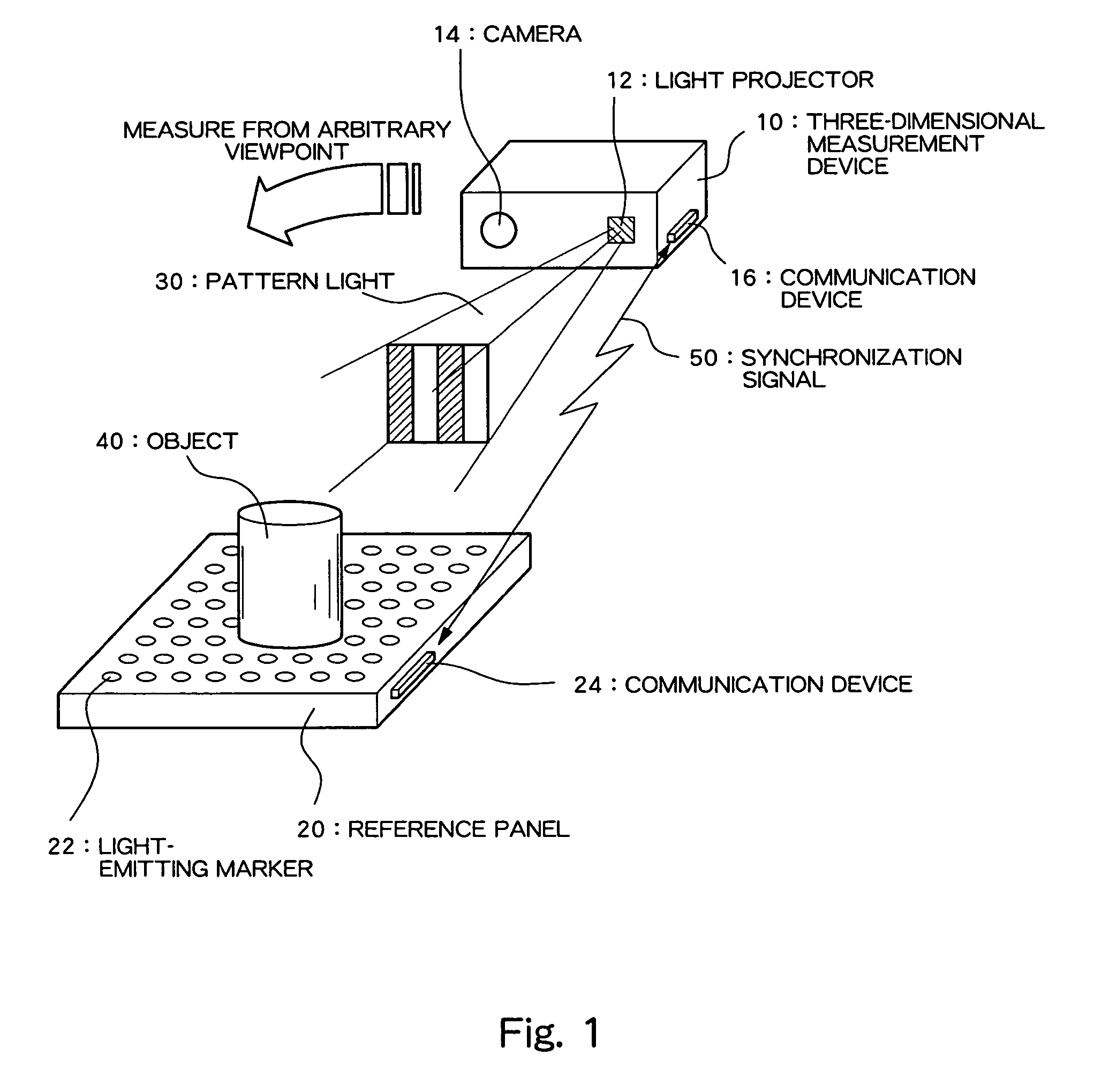
[0026]FIG. 1 is a diagram diagrammatically showing a structure of a three-dimensional measurement system according to a preferred embodiment of the present invention.

[0027]As shown in FIG. 1, the present system comprises a three-dimensional measurement device 10 and a reference panel 20. The three-dimensional measurement device 10 is a device which measures a three-dimensional shape through a spatial coding method, and comprises a light projector 12 which projects pattern light 30 for the spatial coding method, and a camera 14 which captures an image of an object and generates electronic captured image data. Although not shown, the three-dimensional measurement device 10 also comprises a storage device, a CPU (Central Processing Unit), a nonvolatile storage medium storing a measurement process program, etc., and calculates a three-dimensional shape of the object by processing, by...


PUM


Abstract

Camera calibration which is robust against noise factors such as variation in environmental lighting and obstructions is realized. Light-emitting markers, whose on / off states can be controlled, are arrayed in a matrix on a reference panel on which an object is placed. The light-emitting markers blink in accordance with respective switching patterns in synchronism with the frame of continuous imaging of a camera. A three-dimensional measuring instrument determines the time-varying bright-and-dark pattern of a blinking point from the image of each frame and identifies, on the basis of the pattern, to which light-emitting marker each point corresponds. By reference to the identification results, camera calibration is performed, and a coordinate transformation parameter is computed.

Description

CROSS REFERENCE TO RELATED APPLICATIONS[0001]This is a U.S. national stage of application No. PCT / JP2005 / 013357, filed on 21 Jul. 2005. Priority under 35 U.S.C. 119(a) and 35 U.S.C. §365(b) is claimed from Japanese Application No. 2004-212947, filed 21 Jul. 2004, the disclosure of which is also incorporated herein by reference.TECHNICAL FIELD[0002]The present invention relates to a camera calibration system for integrating information based on captured images from free viewpoints in three-dimensional measurement or the like and to a three-dimensional measuring system using the camera calibration system.BACKGROUND ART[0003]As a method for optically determining a three-dimensional shape of an object (target object), in the related art, various methods have been developed and used, including a stereoscopic imaging method, which is a passive shape measurement method; and a light-sectioning method and a spatial coding method, which are active shape measurement methods. However, in all of...

Claims


Application Information

Patent Timeline
Patent Type & Authority Patents(United States)
IPC IPC(8): H04N5/225G06K9/00H04N17/00
CPCG01B11/2504G06T7/0018H04N13/0207H04N13/0253H04N17/002G06T7/80H04N13/207H04N13/254
Inventor SATO, YUKIOSHIBATA, SUSUMU
Owner SPACEVISION
Why Eureka
Try Eureka