Optical network terminal power failure management

Inactive Publication Date: 2010-07-06
VERIZON PATENT & LICENSING INC
View PDF3 Cites 19 Cited by
  • Summary
  • Abstract
  • Description
  • Claims
  • Application Information

AI Technical Summary

Problems solved by technology

However, during a utility company power failure where the output level has been reduced to an emergency level lower than the first level but greater than zero, the controller automatically signals the ONT to power-down completely.

Method used


Image

  • Optical network terminal power failure management
  • Optical network terminal power failure management
  • Optical network terminal power failure management

Examples


Embodiment Construction

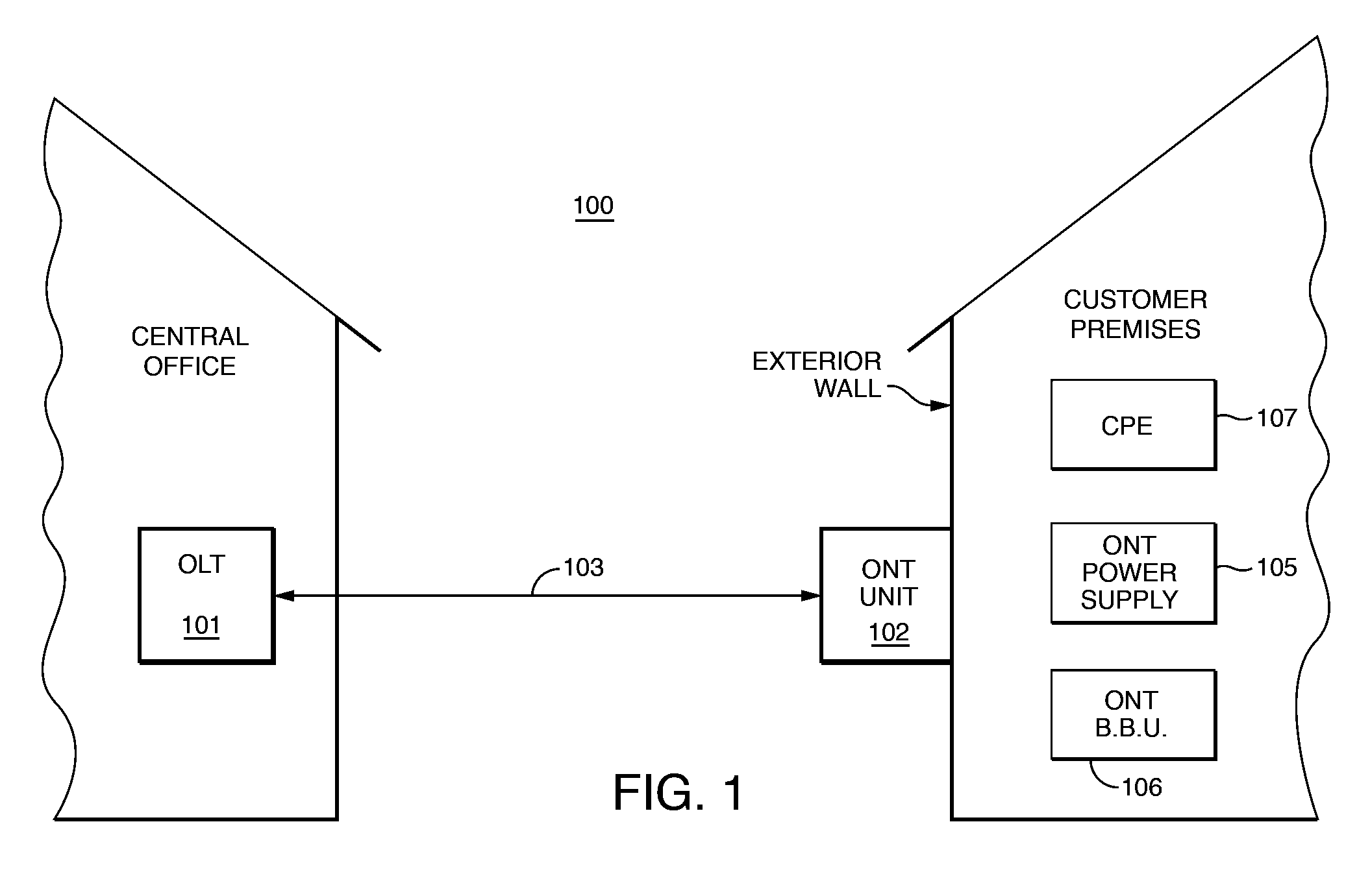
[0016]Referring to FIG. 1, fiber to the premises (FTTP) system 100 is depicted. A telecommunication company's central office is shown at the left-hand side of the drawing, housing optical line terminal (OLT) 101. Other equipment such as switches, routers, server computers, back-up batteries and other functionality (not shown) may be found in a central office.

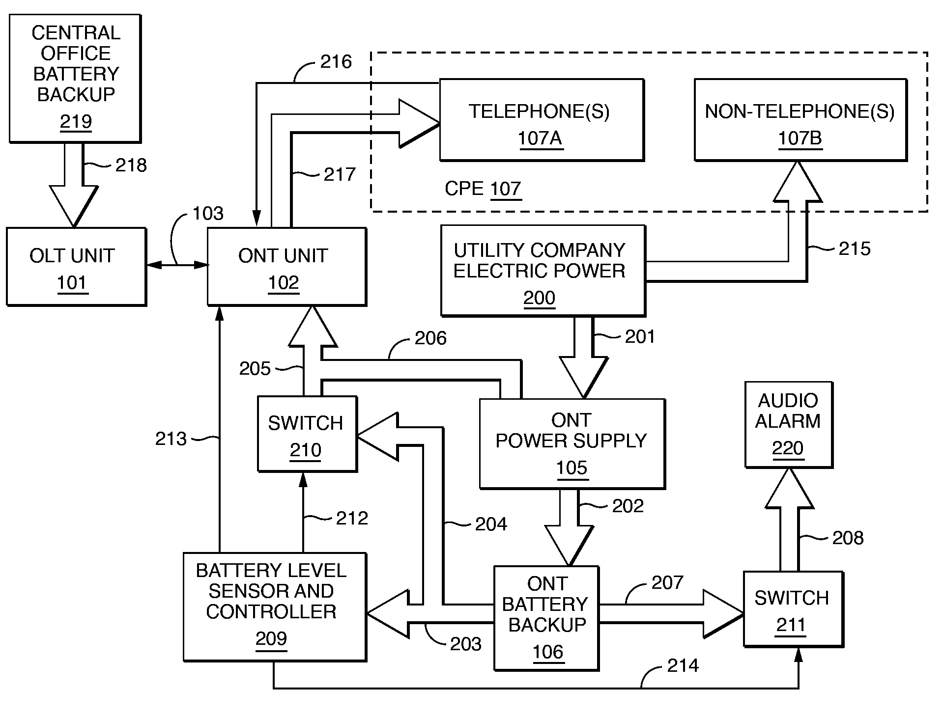
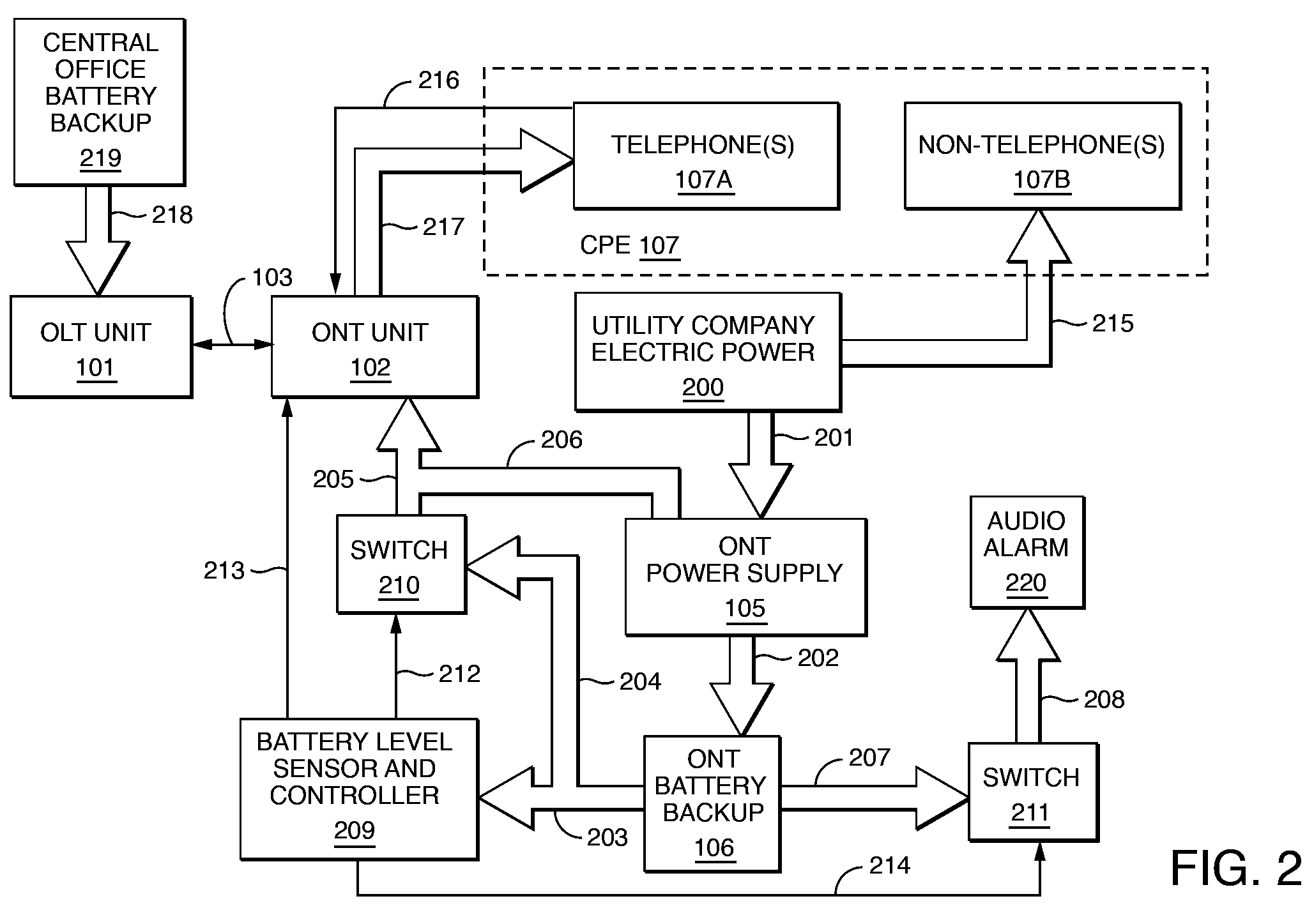
[0017]On the right hand side of the drawing a schematic profile of a customer's premises is provided with optical network terminal (ONT) 102 which may be mounted on the exterior wall of the customer's premises as shown. A typical mounting would put ONT 102 at about four-five feet above ground. ONT 102 may be a standard fiber optical terminal which provides a suitable terminus for fiber optic cable 103. Other system components included within or at the customer premises include ONT power supply105, BBU 106 as battery backup for ONT 102, and customer premises equipment (CPE) 107 which includes any residential-styled communication ...


PUM


Abstract

Optical network terminal (ONT) power failure management. A system for permitting a customer of a telecommunication company, for whom fiber to the premises (FTTP) has been installed, to control operating features associated with operation of a battery backup unit (BBU) which is used, during power failure, for powering the ONT associated with the FTTP installation and the customer's telephone(s). The controlling of these features includes utilization of signal-controlled switches, which are manually over-rideable by the customer, thereby providing the desired operating feature control.

Description

BACKGROUND OF THE INVENTION[0001]1. Field of the Invention[0002]The present invention generally relates to usage of a telecommunication company's fiber to the premises (FTTP) installation at customer premises and, more particularly, relates to the customer's controlling of features associated with a battery backup unit (BBU) used for powering an optical network terminal (ONT) associated with the FTTP installation during power failures.[0003]2. Description of Prior Art[0004]Fiber optic infrastructure is currently being deployed by certain telecommunication companies, including the assignee of the present invention, and being operatively connected to their respective customer bases. Fiber optic telecommunication infrastructure offers many advantages over the old standard copper wire cabling, not the least of which is vastly increased bandwidth. The plain old telephone system (POTS) had operated, and still operates, with copper wiring. POTS is now being made compatible with fiber optic...

Claims


Application Information

Patent Timeline
Patent Type & Authority Patents(United States)
IPC IPC(8): H04J14/00
CPCH04J3/14H04J3/1694H04Q11/0067H04Q2011/0079
Inventor WYNMAN, STANLEY J.
Owner VERIZON PATENT & LICENSING INC
Why Eureka
Try Eureka