Pressurized wire line spool and method for using same in conjunction with a universal radial carrier

a technology of radial carrier and wire line, which is applied in the direction of hoisting equipment, drilling pipes, lifting devices, etc., can solve the problems of reducing the use of affecting the safety of workers, so as to reduce reduce the explosive environment, and eliminate the need for lubricators and stuffing boxes

Inactive Publication Date: 2010-07-13
MORETZ BENNY W +1
View PDF11 Cites 38 Cited by
  • Summary
  • Abstract
  • Description
  • Claims
  • Application Information

AI Technical Summary

Benefits of technology

[0017]Enclosing the cable supply as well as the tool string within a closed housing, the interior of which is in open communication with the well, the well pressure is equalized throughout the housing and all other operations, including lowering and raising of the tool strings and manipulation thereof in the well by means of the flexible cable. Therefore, wire line operations may be conducted without the hazards and disadvantages of more conventional systems. In addition, the need for lubricators and stuffing boxes is eliminated. The need for lengthy sinker weights is also substantially reduced.
[0018]The disclosed pressurized wire line cable supply apparatus may be located remote from the well head and provides a significantly reduced explosive environment within the pressurized cable housing, while allowing easy access to the wire line spool assembly when necessary for inspection and wire replacement.

Problems solved by technology

Since very high pressures may exist within the well, the introduction of such tools and instruments is considerably more difficult and there is always the possibility of blowouts or other serious accidents.
Therefore, in many cases the riser tubing may become quite lengthy.
These conventional systems have a difficult time in preventing leakage around the conductor cable or wire line.
However, any such additional pressure results in additional friction on the wire line or cable, thus preventing the tool string from freely descending into the well bore.
Higher compression applied to the wire line will also often result in serious damage to the slick line or to the wire line electrical conductors.
Thus, stuffing box arrangements are actually self-defeating.
Although various apparatus have been disclosed by the prior art in which wellhead attachments are disclosed that teach the use of elongated closed casing or housing structures in which the tool string, including the entire cable or wire line supply, is enclosed in a manner whereby the housing structure is subjected to the well bore pressure, such apparatus have not gained wide spread acceptance in the art due to several disadvantages.
The wellhead riser attachment and pressurized wire line spool assemblies only allows the riser assembly to be configured in a single plane and do not provide for offsets and multiple radial bends between the well head and the cable spool assembly.
Further, the prior art pressurized wire line spool assemblies fail to provide a satisfactory method for making a rotary electrical connection between the potentially explosive atmosphere of the wire line spool and the electrical supply leading to the down hole instruments.
In addition, no provisions are made in the prior art pressurized wire line spool assemblies for easily adding or changing the wire or cable within a fully enclosed spool without extensive disassembly of the pressurized spool housing.
When it is considered that often tools and instruments must be lowered many thousands of feet into and withdrawn from a well, it will be obvious that the difficulty of running tools rapidly, efficiently, and safely under high pressures will be greatly intensified.
Still further, translating the spool within a pressurized spool housing while rotating the spool under pressure is very difficult in practice, as is maintaining pressure integrity under such high pressures with multiple housing penetrations as required by the prior art.

Method used


Image

  • Pressurized wire line spool and method for using same in conjunction with a universal radial carrier
  • Pressurized wire line spool and method for using same in conjunction with a universal radial carrier
  • Pressurized wire line spool and method for using same in conjunction with a universal radial carrier

Examples


Embodiment Construction

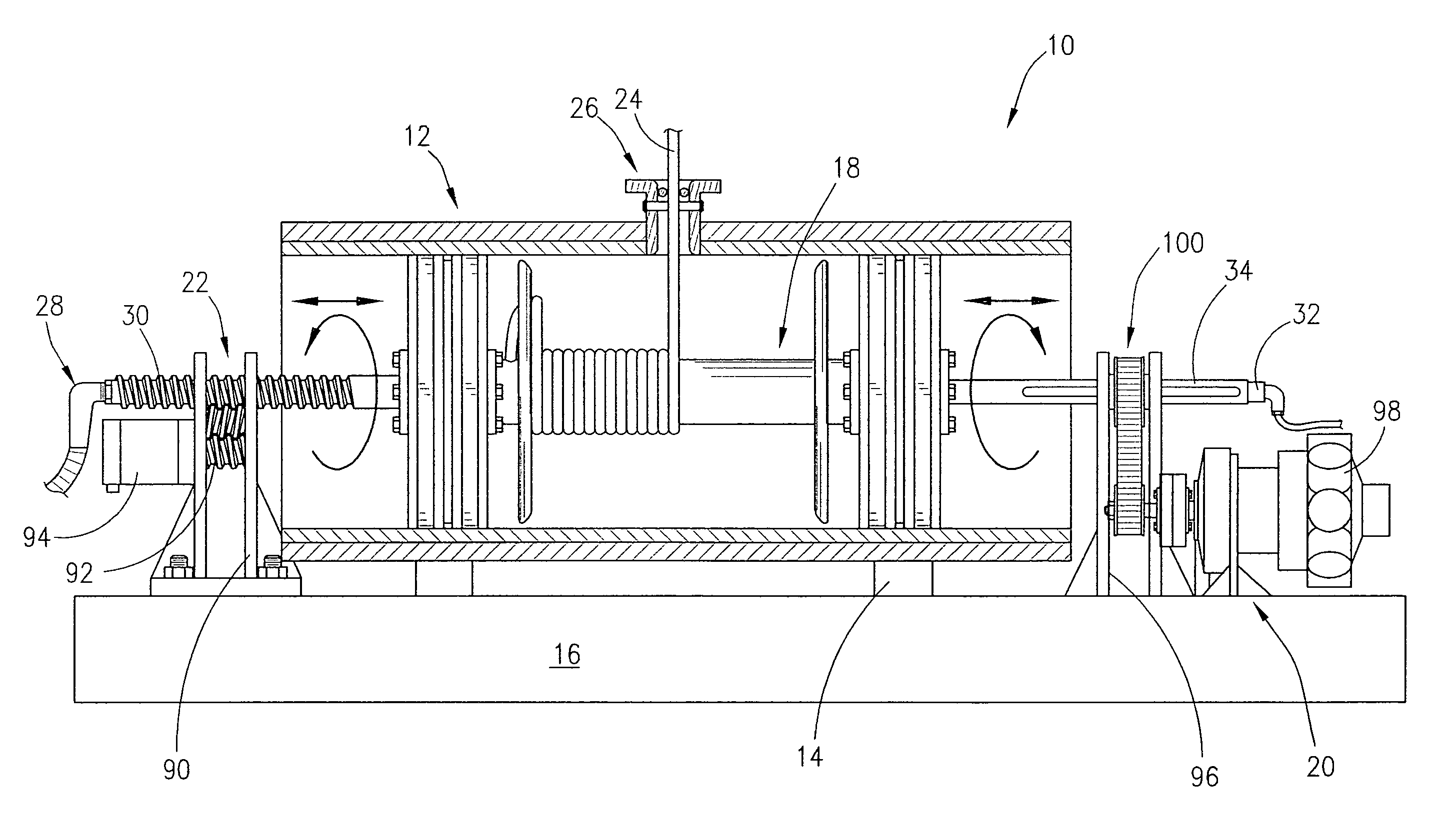
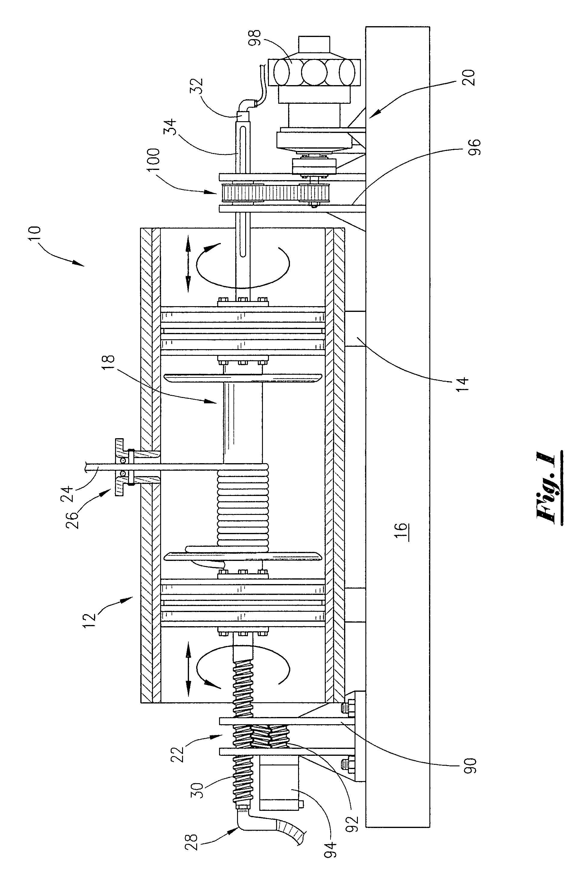
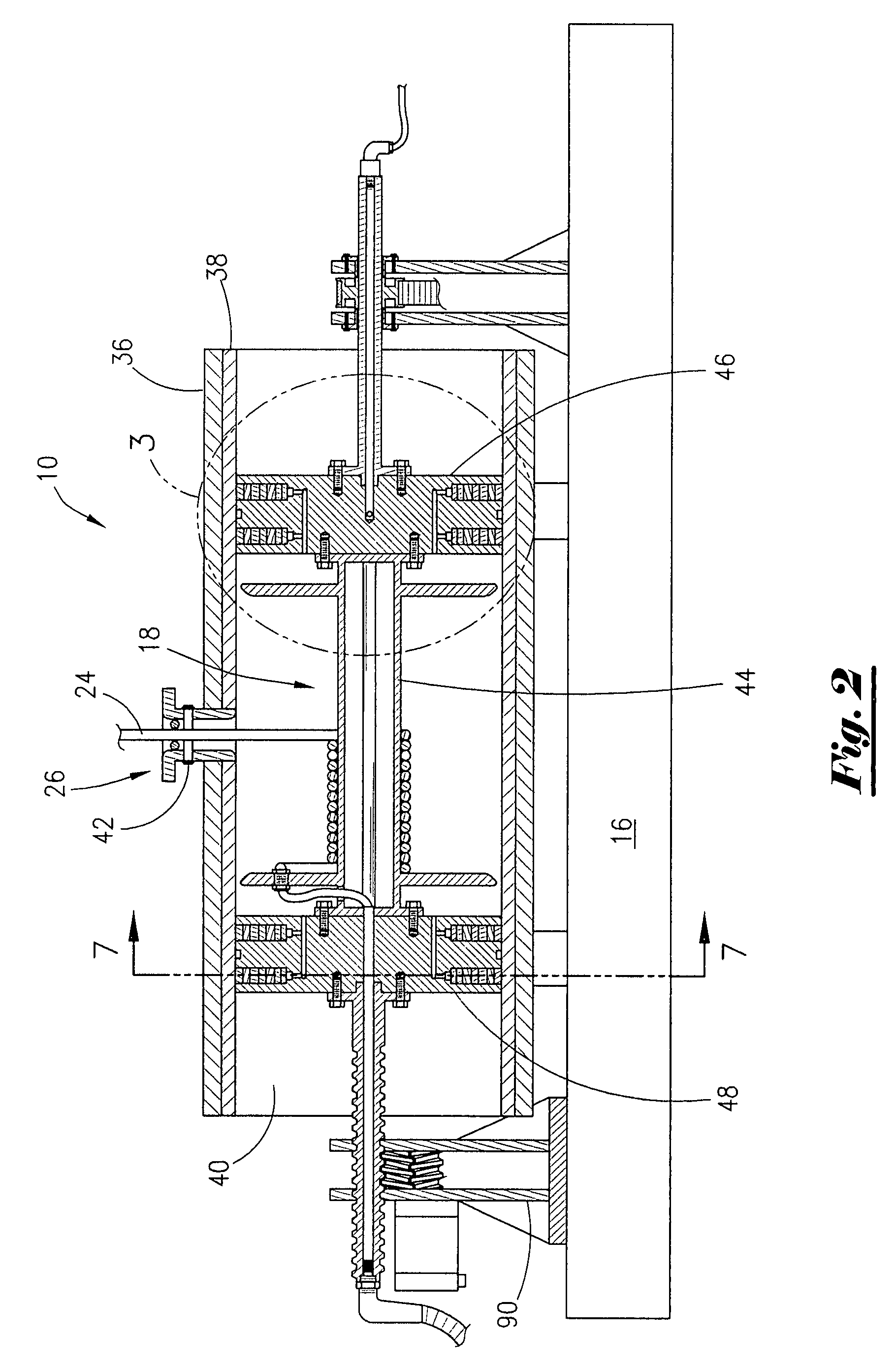
[0038]As first seen in FIG. 1, a pressurable wire line winch assembly 10 is provided that includes an elongated tubular housing assembly 12 rotatably supported upon saddles 14 attached to a base frame structure 16. A spool assembly 18 is rotatably driven by a rotating drive assembly 20 and is translatable within the tubular housing assembly 12 by a translating drive assembly 22.

[0039]A cable or flexible wire 24 is fed into and out of the winch assembly 10 through an enclosed connecting flange collar assembly 26, to be connected to an articulated cable conveyor or carrier to be discussed later herein. An electrical slip ring / input swivel assembly 28, is connected to an electrical supply source and is provided at one end of the translation drive shaft 30 having external threads thereon and a lubrication swivel assembly 32 is connected to a lubrication supply source and is provided at the opposite end of the winch assembly 10 through the keyed rotary drive shaft 34.

[0040]The tubular ho...


PUM


Abstract

A well head attachment is provided having an elongated casing or housing structure in which the tool string, including the entire cable or wire line supply, is pressurized, the housing structure being arranged to place the interior thereof in communication with the well bore in a manner whereby well pressure is equalized throughout the assembly during all operations, utilizing a unique pressure-tight adjustably articulated riser assembly with off-set pivotal radial connections for connection between the wellhead attachment and the pressurized cable-supply reel, thus the need for lengthy sinker weights, lubricators and stuffing boxes is reduced or eliminated.

Description

1. FIELD OF THE INVENTION[0001]This invention relates generally to wire line winch apparatus and more particularly to wire line winches in oil and gas communication with well bores under pressure by way of pressurized radial wire line conveyors for pivotally conveying wire lines from the winch assembly to the well bore in complex configurations.2. GENERAL BACKGROUND[0002]Wire line operations generally relate to the attachment of tubular members to a wellhead through which flexible cables called slick lines and wire lines (electrical conductor cables) and tools connected and / or supported thereby are inserted into the well bore while the well is under pressure.[0003]As those in the art are aware, during operation of an oil or gas well, it often becomes necessary to introduce various tools and instruments into the well bore and operate same within the down hole tubing environment while the well is under pressure. These tools and instruments are ordinarily inserted into the well by usin...

Claims


Application Information

Patent Timeline
Patent Type & Authority Patents(United States)
IPC IPC(8): B66D1/00
CPCB66D1/39E21B19/22
Inventor MORETZ, BENNY W.MONTGOMERY, ROBERT N.
Owner MORETZ BENNY W
Why Eureka
Try Eureka