Illuminated plastic fuel tank

a technology of illuminating and fuel tanks, applied in the direction of rigid containers, machines/engines, liquid/fluent solid measurement, etc., to achieve the effect of changing the flammability or contamination characteristics of the tank, increasing the hazard of fire, and not increasing the hazard of contaminating water

Inactive Publication Date: 2010-07-13
GROOVER PHILIP GUY
View PDF12 Cites 14 Cited by
  • Summary
  • Abstract
  • Description
  • Claims
  • Application Information

AI Technical Summary

Benefits of technology

[0007]An embodiment of the invention is an illuminable tank comprising a partially translucent tank having partially translucent side walls and an upper portion; and an illumination apparatus. Activation of the illumination apparatus is at the user's discretion, for instance to determine the level of liquid in the tank, to make the tank more visible at night, and to light the area surrounding the tank's mouth and a spout, if so equipped. The illumination apparatus does not change the flammability or contamination characteristics of the tank, so that if the tank is used to store, carry or dispense flammable fuel it can be illuminated without increasing the hazard of having a fire. If the tank is used to store, carry or dispense water it can be illuminated without increasing the hazard of contaminating the water. The illumination apparatus comprises an electrical circuit with a plurality of light emitting devices, where at least one first light emitting device is operatively mounted on the upper portion of the translucent tank. The first light emitting device is directed toward the interior of the tank, therein backlighting the tank and illuminating a visible level line at an interface of a surface of the liquid in the tank and the space above the surface.

Problems solved by technology

The sensors cause the illumination apparatus to automatically shut off if a problem, such as overheating, is detected.

Method used


Image

  • Illuminated plastic fuel tank
  • Illuminated plastic fuel tank
  • Illuminated plastic fuel tank

Examples


Embodiment Construction

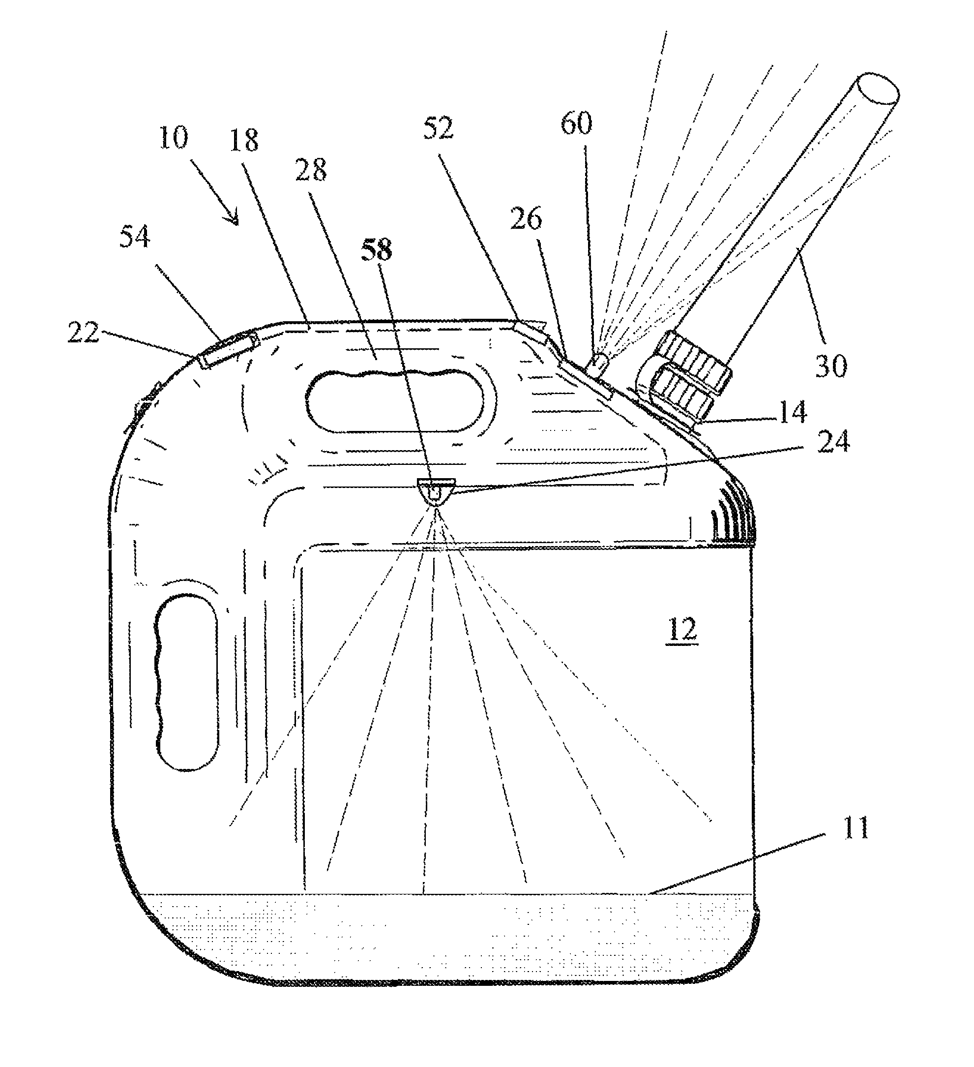
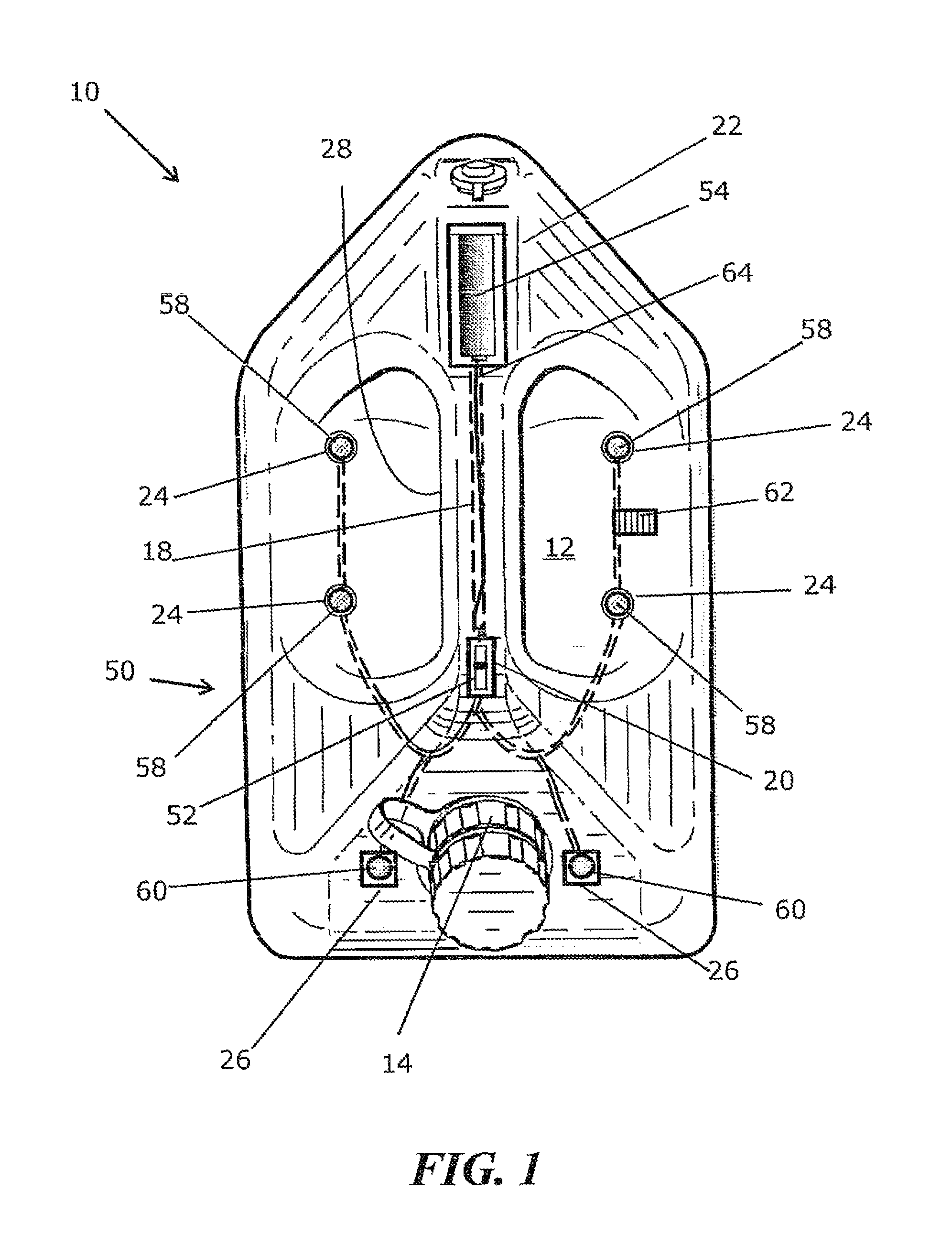
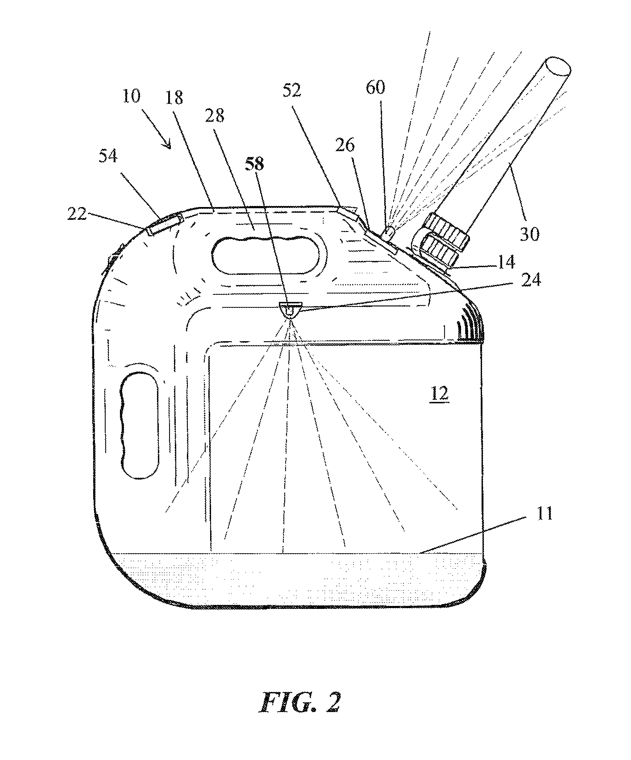
[0019]The illuminable tank 10 as illustrated in FIG. 1 is a portable fuel tank. It is comprised of a partially translucent tank 12 having walls composed of a plastic material, typically a pigmented thermoplastic material, that are partially translucent. The partially translucent tank incorporates an illumination apparatus that is manually actuated. The illumination apparatus can be self-contained or built-into the portable fuel tank. In the illustrated built-into embodiment, the illumination apparatus comprises an electrical circuit with a plurality of light emitting devices, where at least one first light emitting device is mounted in a receptacle on the upper portion of the partially translucent tank. The first light emitting device is directed toward the interior of the tank, therein backlighting the tank and illuminating a visible level sine at an interface of a surface of the liquid in the tank and the space above the surface. There is also at least one second light emitting de...


PUM

PropertyMeasurementUnit
voltageaaaaaaaaaa
opacityaaaaaaaaaa
translucentaaaaaaaaaa

Abstract

The invention is an illuminable tank that includes a partially translucent plastic tank and an illumination apparatus. The illuminable tank enables a user to determine the level of liquid in the tank, to make the tank more visible at night, and to light the area surrounding the tank's mouth and a spout. The illumination apparatus has a magnetic reed switch and an electrical circuit with a plurality of light emitting devices that are directed toward the interior of the tank, therein backlighting the tank and illuminating a visible level line at an interface of a surface of the liquid in the tank and the space above the surface. There can also be external lights which provide a cone of light for the spout. The illumination apparatus is explosion proof, and the illuminable plastic tank can be used to store, carry and dispense all commercial retail fuels.

Description

CROSS REFERENCE TO RELATED PATENT APPLICATIONS[0001]The application claims the benefit of the priority filing date of the provisional application bearing Ser. No. 60 / 921,772, which was filed on Apr. 4, 2007.BACKGROUND OF THE INVENTION[0002]1) Field of the Invention[0003]The invention relates to fuel tanks, and more particularly to an illumination apparatus and an illuminable tank that is a partially translucent tank having a lighted interior that facilitates determining the level of liquid in the tank and an illuminated spout for minimizing spillage.[0004]2) Prior Art[0005]Plastic tanks, particularly those used for storing and conveying fuels (gasoline, kerosene, diesel fuel), are typically brightly colored so that they can be easily seen in daylight. Usually they are color coded, such that gasoline is in a red tank, kerosene is in a yellow tank, and diesel is in a blue tank. The color coding connotes that the contents are hazardous, because the liquid contained, therein is highly f...

Claims


Application Information

Patent Timeline
Patent Type & Authority Patents(United States)
IPC IPC(8): F21V33/00G01F23/00B60Q1/00B67C3/00F21V9/12F21V5/00B65D5/66
CPCF21V23/04G01F23/02G01F23/292F21W2131/411F21Y2101/02F21V33/00F21Y2115/10
Inventor GROOVER, PHILIP GUY
Owner GROOVER PHILIP GUY
Why Eureka
Try Eureka