
Modular system for the control of compression systems

a compression system and module technology, applied in the direction of pump control, pump components, piston pumps, etc., can solve the problems of not being able to adapt to other manufacturers' compressors, unable to verify control efficiency, and ineffective use of compressed air, etc., to achieve maximum reliability, good network performance, and favorable cost

Inactive Publication Date: 2010-07-13
SARLIN HYDOR
View PDF7 Cites 0 Cited by
  • Summary
  • Abstract
  • Description
  • Claims
  • Application Information

AI Technical Summary

Benefits of technology

[0011]In the system of the invention, one or more compressors and the associated secondary treatment apparatus, connected to one or more compressed air networks or equivalent, are controlled and monitored. The system of the invention is based on a modular technique as far developed as possible, utilization of parameters and inter-modular fault diagnostics. By additionally combining these features with a possibility of remote monitoring and programmability, a maximally reliable solution of favorable cost is guaranteed. In addition, the system contains useful analyzing and reporting features that make it possible to verify the benefit provided by the system and to maintain a good performance of the network and to improve it on a continuous basis.
[0012]Due to its architecture, the system can be constructed from standard components produced by automation manufacturers. The invention allows a decisive reduction to be achieved in the amount of work required at installation time.

Problems solved by technology

In addition, compressed air is a critical production factor, and consequently quality problems appearing in compressed air are in many cases economically much more significant than the energy spent on producing it.
Ineffective use of compressed air has been found to be a significant problem in many countries.
Among the most typical solutions are standard controllers provided by compressor manufacturers and having their own control programs, which can not be customized to suit other manufacturers' compressors and which comprise no verification of efficiency of control.
The prices of customizable solutions are high due to the large amount of programming work needed, among other things.
Under these circumstances, the equipments have to be built in small production series, and consequently they are expensive.
A large proportion, even 80% of maintenance visits associated with control systems are attributable to a misuse failure.
When users are changed out for new ones, the training they have once received is no longer useful.
This leads to a situation where, in the course of time, even a well performing system does not necessarily answer its purpose.

Method used


Image

  • Modular system for the control of compression systems
  • Modular system for the control of compression systems

Examples


Embodiment Construction

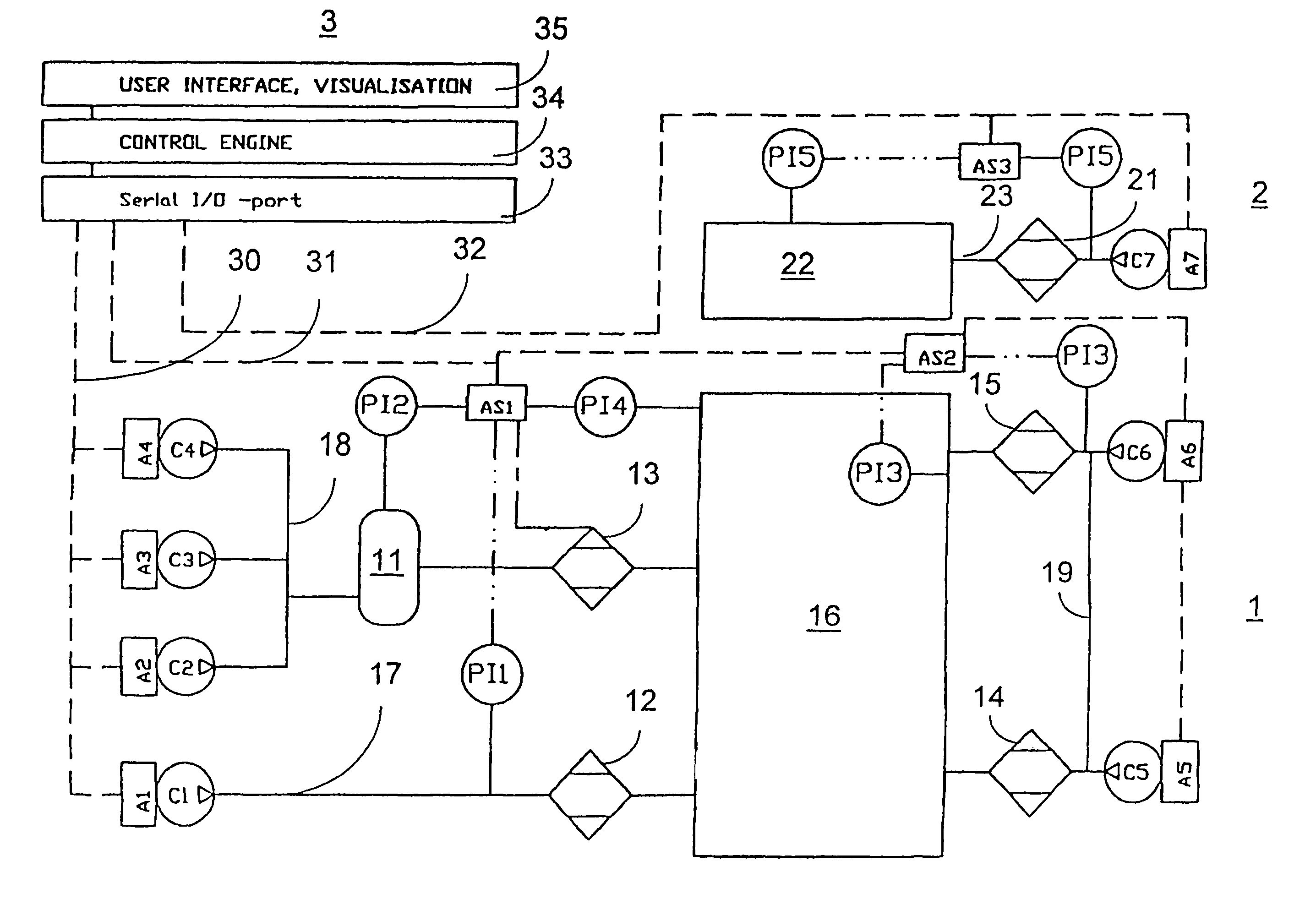
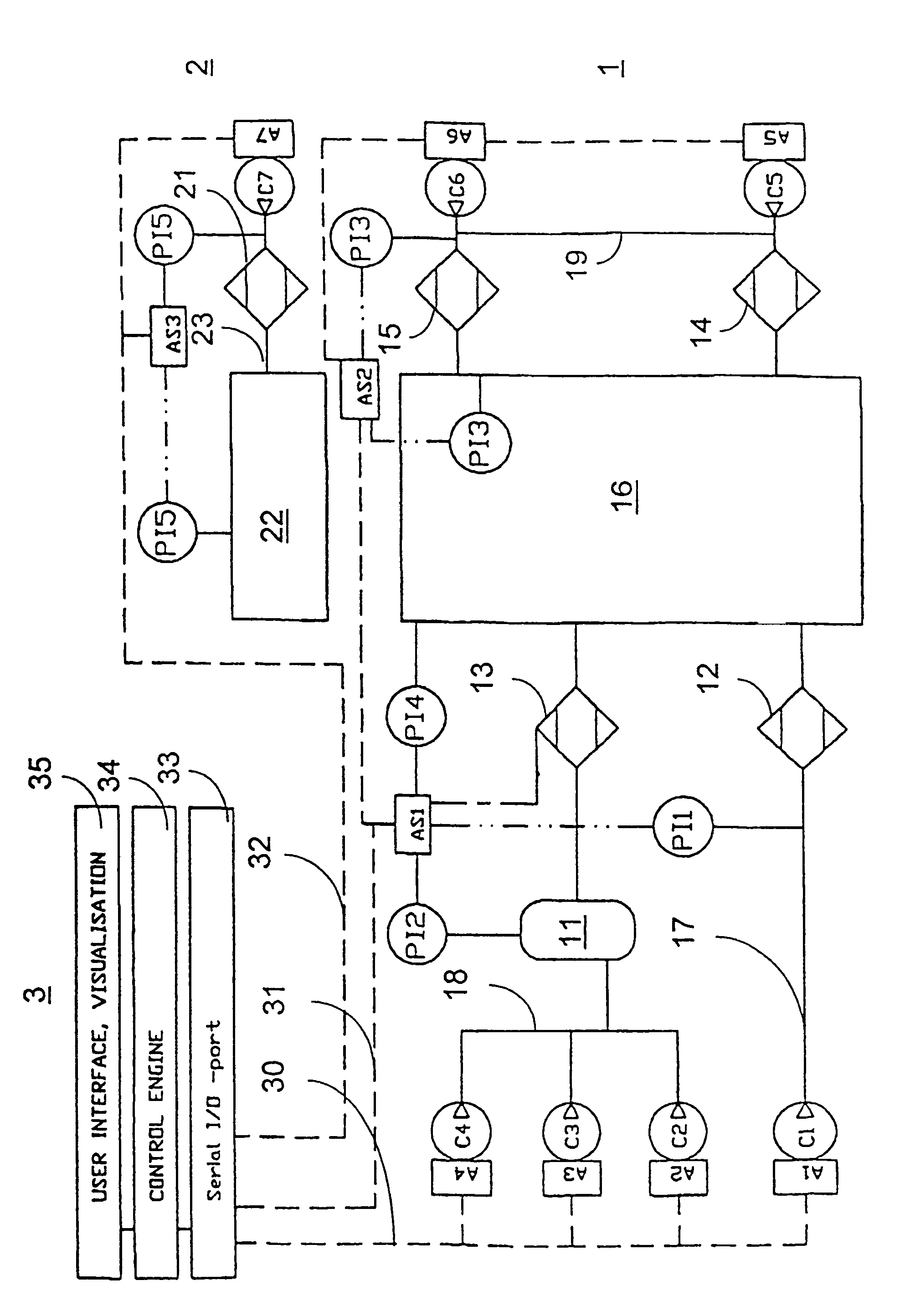
[0014]The pneumatic system comprises two compressed air networks 1, 2, which are connected to a control system that controls them. The first network 1 comprises six compressors C1-C6 with their controllers A1-A6, a pressure tank 11 connected to three compressors C2-C4, four secondary treatment units 12-15, a place of consumption 16 and piping systems 17-19 for their interconnection. The second network 2 correspondingly comprises one compressor C7 with its controller A7, a secondary treatment unit 21, a place of consumption 22 and a piping system 23 for their interconnection.

[0015]In addition, both networks are provided with pressure sensors PI1-PI5, of which PI1 is connected to the pressure tank piping 17 between compressor C1 and secondary treatment unit 12, PI2 to the pressure tank, 11, PI3 to the piping 19 between compressors C5, C6 and secondary treatment unit 14, 15, PI3 and PI4 to the place of consumption 16 and PI5 to the piping 23 between compressor C7 and secondary treatmen...


PUM


Abstract

A modular system for the control of at least one compression system for the compression a fluid medium, said compression system comprising compressors (C1-C7) and their controllers (A1-A7) for the compression of the fluid medium, secondary treatment devices for the treatment of the medium delivered from the compressors, and piping systems (17-19, 23) for conducting the fluid medium to a place of consumption (16, 22), said control system comprising a control unit (3) containing a data processing system (34) for controlling the compression system, a user interface (35) including a display associated with it and transmission means for the transmission of control data between the control unit, the controllers and pressure sensors. The transmission means consist of data communication buses, preferably serial communication buses (30-32) and a data communication port unit (33) serving to connect the bus to the control unit (34). The controllers and pressure sensors are connected to common data communication buses.

Description

CROSS-REFERENCE TO RELATED APPLICATIONS[0001]This is a continuation of application Ser. No. 10 / 470,996, filed Oct. 14, 2003, which was a national phase filing of PCT / FI02 / 00082, filed 4 Feb. 2002, which was based on Finland Application No. 20010199, filed Feb. 2, 2001. All priorities are claimed.BACKGROUND OF THE INVENTION[0002]1. Field of the Invention[0003]The present invention relates to a method for controlling a compression system for the compression of a fluid medium.[0004]2. The Prior Art[0005]In industrialized countries, about 10% of the electric energy consumed by industry is spent on the production of compressed air. In addition, compressed air is a critical production factor, and consequently quality problems appearing in compressed air are in many cases economically much more significant than the energy spent on producing it. Ineffective use of compressed air has been found to be a significant problem in many countries.[0006]In the compression systems of compressed air n...

Claims


Application Information

Patent Timeline
Patent Type & Authority Patents(United States)
IPC IPC(8): F04B49/06
CPCF04B49/065F04B2205/05
Inventor SAARINEN, VESAVALOVIRTA, LAURINYMAN, SAMI
Owner SARLIN HYDOR
Learn More