Process and apparatus for feeding cementitious slurry for fiber-reinforced structural cement panels

a technology of reinforced structural cement and feeder apparatus, which is applied in the direction of surface layering apparatus, press section, manufacturing tools, etc., can solve the problems of insufficient structural strength, and achieve the effect of enhancing strength characteristics and reducing processing time for panel production equipmen

Active Publication Date: 2010-07-13
UNITED STATES GYPSUM CO
View PDF157 Cites 13 Cited by
  • Summary
  • Abstract
  • Description
  • Claims
  • Application Information

AI Technical Summary

Benefits of technology

[0023]The vibrating gate is disposed in operational relationship to the metering roll for controlling the thickness of a layer of slurry drawn from the nip upon an outer surface of the metering roll. It is theorized that the vibrating gate contacts the slurry and imparts shear forces to the thixotropic slurry to keep the slurry fluid. This assists in avoiding buildup of slurry at the ends of the roller and premature setting of the slurry in the headbox (slurry feed apparatus).
[0025]In its process respects the present invention provides a process for providing a cementitious slurry with improved fluidity through use of a vibrating gate to impart shear forces to the slurry. This assists in obtaining uniform deposition of slurries on moving web without premature setting over a wider range of cement and water slurries with a greater range of water to cement solids. The present invention advantageously avoids significant build-up of slurry setting up in the corners of the headbox at the ends of the rolls to facilitate achieving even distribution of the slurry from the headbox (slurry feed apparatus).
[0028]In a preferred embodiment, multiple layers of chopped individual loose fibers are deposited relative to each layer of deposited slurry. The preferred sequence is that a layer of loose fibers are deposited, upon either the moving web or existing slurry, followed by a layer of slurry, then another layer of fibers. Next, the fiber / slurry / fiber combination is subjected to embedding to thoroughly mix the fibers in the slurry. This procedure has been found to permit the incorporation and distribution of a relatively larger amount of slurry fibers throughout the slurry using fewer slurry layers. Thus, panel production equipment and processing time can be reduced, while providing an SCP panel with enhanced strength characteristics.

Problems solved by technology

However, a drawback of such conventional panels is that they do not have sufficient structural strength to the extent that such panels may be comparable to, if not stronger than, structural plywood or oriented strand board (OSB).

Method used


Image

  • Process and apparatus for feeding cementitious slurry for fiber-reinforced structural cement panels
  • Process and apparatus for feeding cementitious slurry for fiber-reinforced structural cement panels
  • Process and apparatus for feeding cementitious slurry for fiber-reinforced structural cement panels

Examples


second embodiment

of a Production Line

[0149]The incorporation of a volume fraction of loose fibers distributed throughout the slurry 46 is an important factor in obtaining desired panel strength. Thus, improved efficiency in incorporating such fibers is desirable. It is believed the system depicted in FIG. 1 in some cases requires excessive numbers of slurry layers to obtain an SCP panel having sufficient fiber volume fraction.

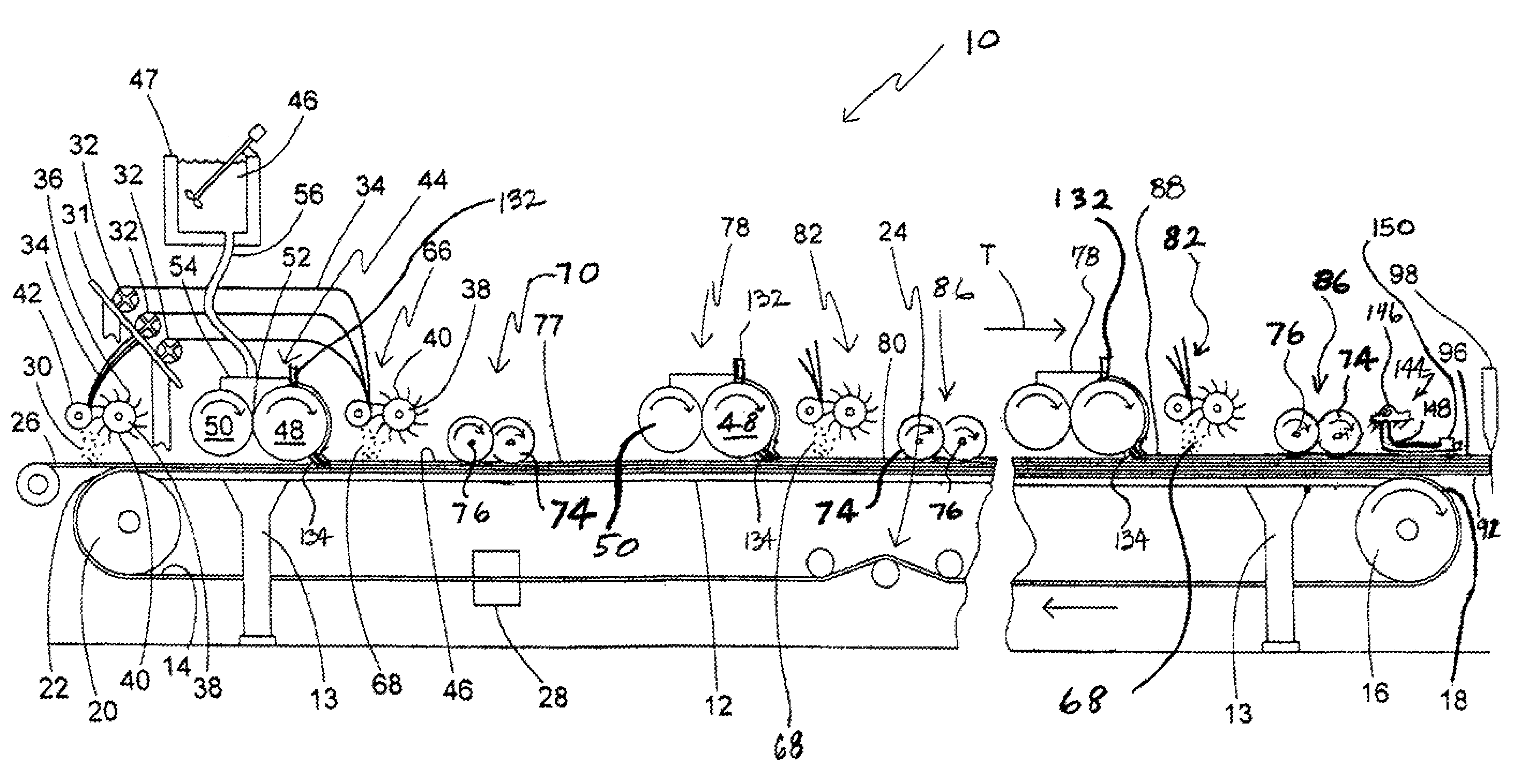
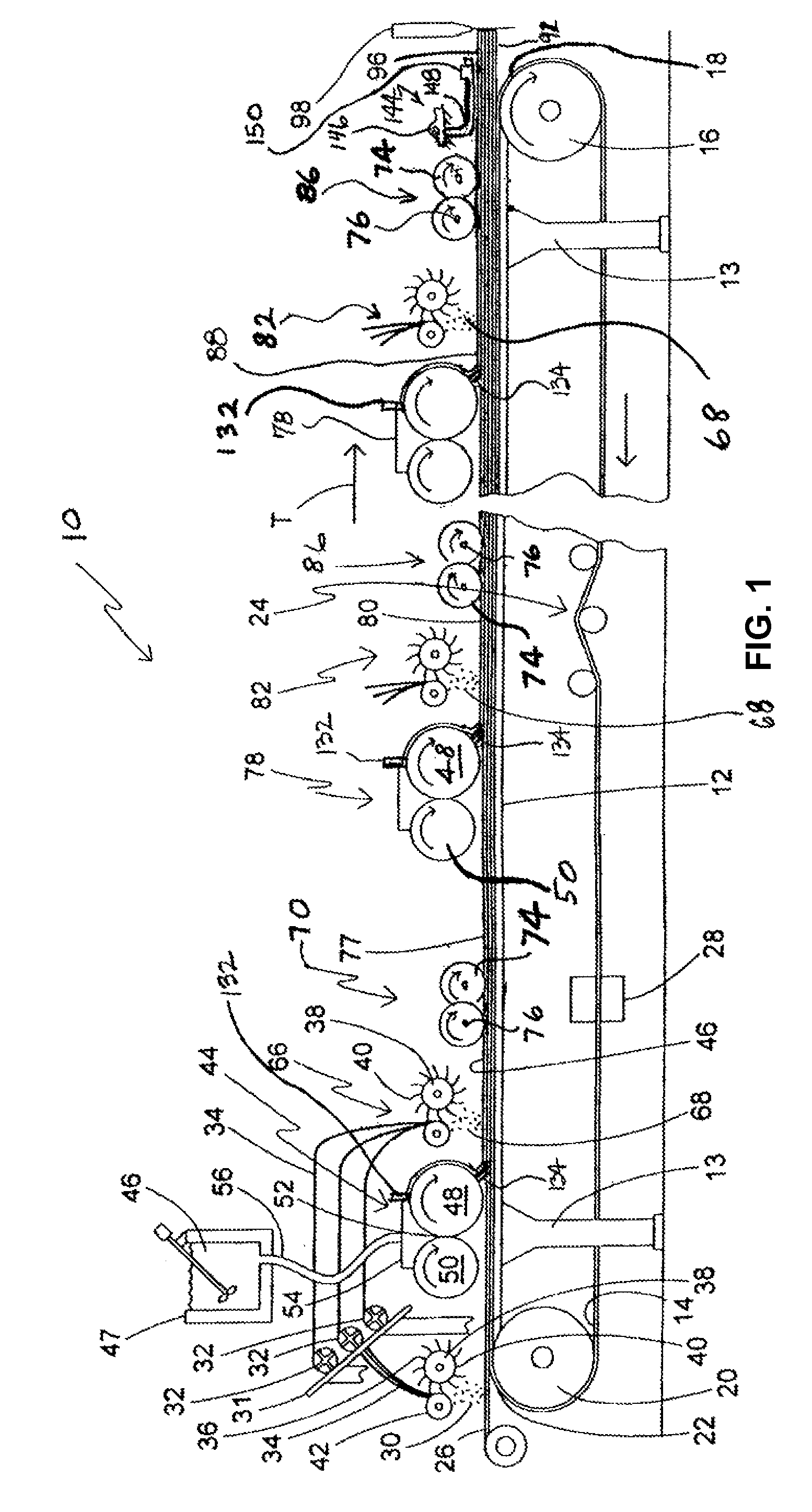
[0150]Accordingly, an alternate SCP panel production line or system is illustrated in FIG. 13 and is generally designated 130 for producing high-performance, fiber reinforced SCP panels incorporating a relatively high volume of fibers per slurry layer. In many cases, increased levels of fibers per panel are obtained using this system. While the system of FIG. 1 discloses depositing a single discrete layer of fibers into each subsequent discrete layer of slurry deposited after the initial layer, the production line 130 includes a process of building up multiple discrete reinforc...

example 1

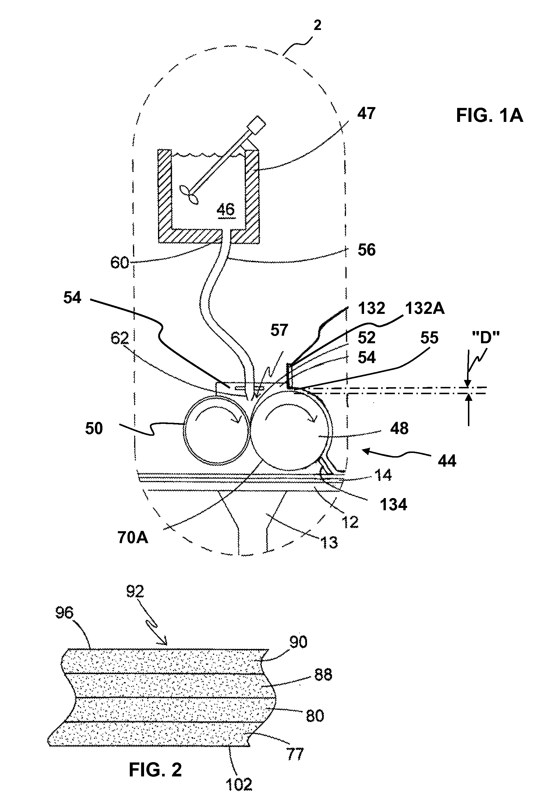
[0213]Referring now to FIG. 2, a fragment of the SCP panel 92 made from fibers and a slurry. The cements portion of the slurry comprises 65 wt. % Calcium sulfate alpha hemihydrate, 22 wt. % Type III Portland cement, 12 wt. % Silica Fume, and 1 wt. % hydrated lime. The liquid portion of the slurry comprises 99.19 wt. % water and 0.81 wt. % ADVACAST superplasticizer by W.R. Grace and Co. The liquid:cement weight ratio was 0.55 and the Aggregate (EXTENDOSPHERES SG microspheres):Cement weight ratio was 0.445.

[0214]The slurry was produced according to the present process, using the present system, and is shown to have four slurry layers, 77, 80, 88 and 90. This panel should be considered exemplary only in that a panel 92 produced under the present system may have one or more layers. By using the above mathematical relationships, the slurry layers 77, 80, 88 and 90 can have different fiber volume fractions. For example, skin or face layers 77, 90 have a designated fiber volume fraction Vf...

example 2

[0219]The residence time of the wet slurry in various embodiments of a vertical mixing chamber have been empirically determined by determining the residence time of a red dye tracer added to the slurry to completely exit the vertical chamber. Tests were conducted to determine residence time in the vertical mixing chambers using a red dye tracer added to the water and powder slurry as it enters the vertical chamber. The cementitious slurry had substantially the same composition as described above for Example 1.

[0220]The equipment used was a digital scale to weigh the slurry, a bucket to catch the slurry and a stop watch to measure the elapsed time of the various points. A mixer was used with three different mixing chamber designs as listed in Tables 2-4 as a 12 inch Mixer, an 8 inch Extended Mixer, and an 8 inch Stock Mixer.

[0221]The 8 inch Stock Mixer is a DUO MIX 2000 mixer which is similar to that of FIG. 3A disclosed in U.S. patent application Ser. No. 11 / 555,655, entitled APPARA...


PUM

PropertyMeasurementUnit
sizeaaaaaaaaaa
diameteraaaaaaaaaa
residence timeaaaaaaaaaa

Abstract

A head-box for depositing slurry upon a moving web including a main metering roll, a companion roll disposed in closely spaced relation to the metering roll and a vibrating gate which forms a nip between the metering roller and the gate. The nip is arranged to retain a supply of the slurry, and the rolls are driven so slurry retained in the nip progresses over an upper outer peripheral surface of the metering roll to be deposited upon the web. Also, preferably included is a doctor blade disposed in operational relationship to the metering roll for directing the slurry downwardly from the outer metering roll surface to a point above the surface of a carrier for a fiberglass layer upon which the slurry layer is deposited. The vibrating gate and doctor blade may be pivotally mounted to either side of the surfaces of the head-box.

Description

CROSS REFERENCE TO RELATED APPLICATIONS[0001]This application is related to co-pending:[0002]U.S. patent application Ser. No. 11 / 555,655, entitled METHOD FOR WET MIXING CEMENTITIOUS SLURRY FOR FIBER-REINFORCED STRUCTURAL CEMENT PANELS, filed Nov. 1, 2006;[0003]U.S. patent application Ser. No. 11 / 555,658, entitled APPARATUS AND METHOD FOR WET MIXING CEMENTITIOUS SLURRY FOR FIBER-REINFORCED STRUCTURAL CEMENT PANELS, filed Nov. 1, 2006;[0004]U.S. patent application Ser. No. 11 / 555,661, entitled PANEL SMOOTHING PROCESS AND APPARATUS FOR FORMING A SMOOTH CONTINUOUS SURFACE ON FIBER-REINFORCED STRUCTURAL CEMENT PANELS, filed Nov. 1, 2006;[0005]U.S. patent application Ser. No. 11 / 555,665, entitled WET SLURRY THICKNESS GAUGE AND METHOD FOR USE OF SAME, filed Nov. 1, 2006;[0006]U.S. patent application Ser. No. 11 / 591,793, entitled MULTI-LAYER PROCESS AND APPARATUS FOR PRODUCING HIGH STRENGTH FIBER-REINFORCED STRUCTURAL CEMENTITIOUS PANELS WITH ENHANCED FIBER CONTENT, filed Nov. 1, 2006; and[...

Claims


Application Information

Patent Timeline
Patent Type & Authority Patents(United States)
IPC IPC(8): D21F1/18D21F1/08
CPCB28B5/027B28B7/364B28C5/404B28B19/0015B28C5/365B28B13/022
Inventor FRANK, WILLIAM A.STIVENDER, EUGENE SCOTTGEORGE, LLOYD M
Owner UNITED STATES GYPSUM CO
Why Eureka
Try Eureka