Method and device for correction motion in imaging during a medical intervention

a technology of motion correction and medical intervention, applied in the field of medical intervention, can solve the problems of static image, errors in overlaid representation with projected 3d image, etc., and achieve the effect of improving the target accuracy of the biopsy itsel

Active Publication Date: 2010-07-20
SIEMENS HEALTHCARE GMBH
View PDF13 Cites 34 Cited by
  • Summary
  • Abstract
  • Description
  • Claims
  • Application Information

AI Technical Summary

Benefits of technology

[0005]The object of the present invention is hence to disclose a method and a device for correcting motion in imaging during a medical intervention with both of whose aid errors of said type are avoided in the overlaid representation of the 2D fluoroscopic images by means of a suitable representation of the 3D image.
[0015]The present method and associated device are suitable for imaging during any interventions during which motion in the target area has to be corrected. Besides movements due to respiration, this relates also to other organ movements, for example heartbeats during cardiological or electro-physiological interventions, or the patient's own movements. The method described and the associated device offer particular advantages especially in connection with abdominal applications such as, for example, liver biopsies. Movements of the liver being relatively decoupled from the surface of the skin, motion cannot here be corrected based on artificial landmarks secured to the skin's surface. On the other hand, several punctures are often necessary for a liver biopsy in order to reach the desired target location. Inserting a puncture needle before the 3D image recording is made enables the physician to be provided with error-free image information for the remainder of the intervention so that targeting accuracy for the biopsy itself will be improved.

Problems solved by technology

A problem with 2D / 3D registration, particularly in the case of abdominal applications such as, for instance, liver biopsies, is that the preoperatively recorded 3D image is static, whereas respiratory movements are clearly discernible in the 2D fluoroscopic images.
That leads to errors in the overlaid representation with the projected 3D image.

Method used


Image

  • Method and device for correction motion in imaging during a medical intervention
  • Method and device for correction motion in imaging during a medical intervention
  • Method and device for correction motion in imaging during a medical intervention

Examples


Embodiment Construction

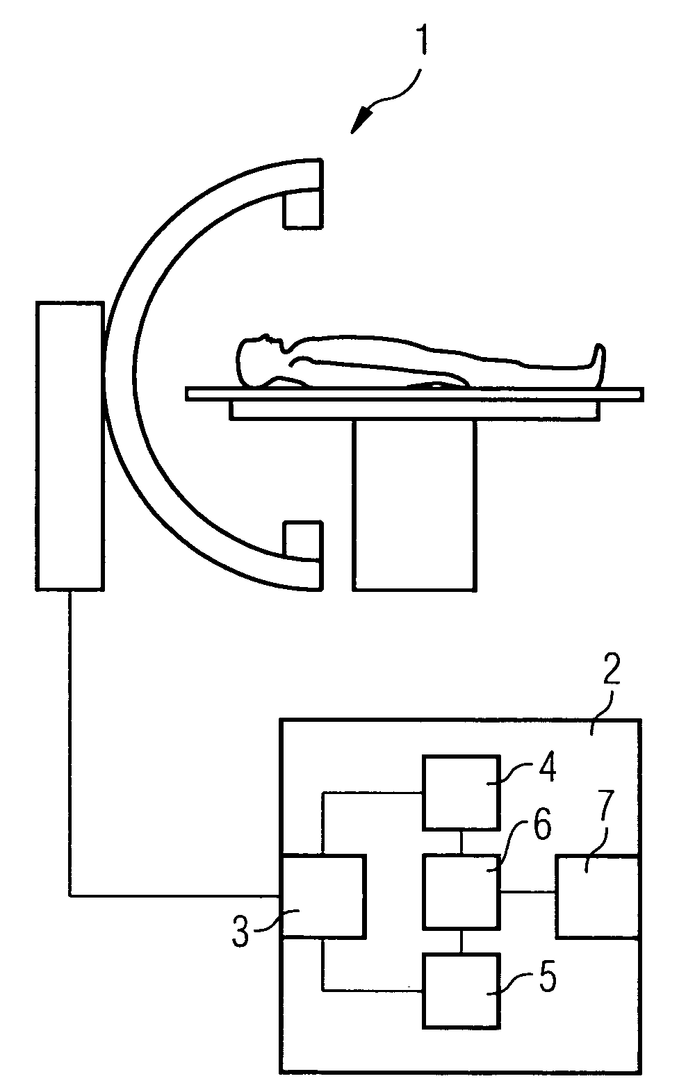
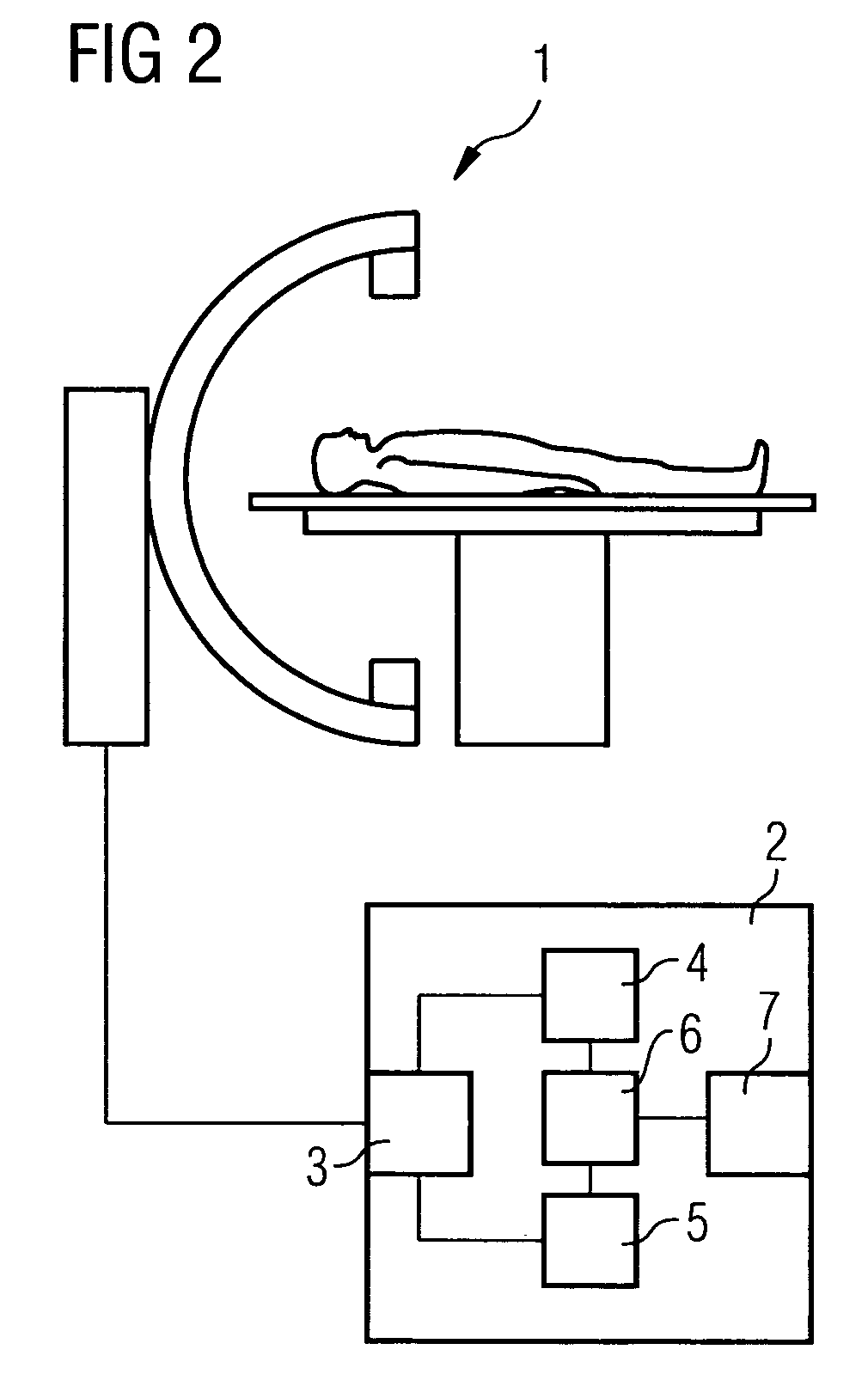
[0021]The method is explained in the first example that follows with the aid of a liver intervention during which a catheter is navigated into the liver. Both in this example and in that which follows, the patient is positioned on a C-arm device by means of which both the 3D image and the 2D fluoroscopic images are recorded.

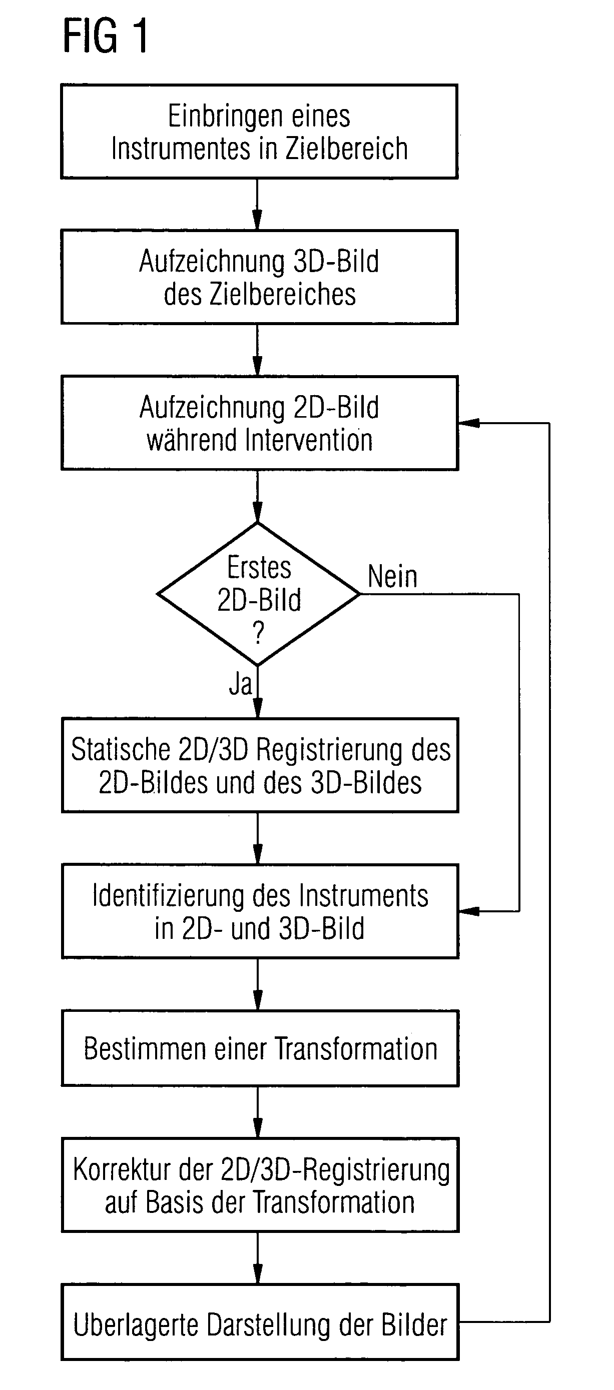
[0022]The physician first navigates the catheter into the liver. Using the C-arm device, the physician then records a 3D angiographic image of the liver containing the catheter. FIG. 4 is an example of a 3D angiographic image of said type in which the catheter 8 is discernible. The catheter 8 is marked in said reconstructed 3D image by the physician or segmented automatically to distinguish it from other structures.

[0023]The physician then performs the intervention while 2D fluoroscopic recordings are being made using the C-arm device. The first 2D fluoroscopic image is therein first registered using the known system parameters from which the geometry data or, as...


PUM


Abstract

The present invention relates to a method and a device for correcting motion in imaging during a medical intervention, by which method a 3D tomographic image of a target area for the intervention is first recorded while there are one or more medical instruments in the target area that will remain there during the intervention. During the intervention 2D fluoroscopic images of the target area are recorded and registered with the 3D image. The registration is therein adjusted for each 2D fluoroscopic image in realtime based in each case on the one or more instruments. The 2D fluoroscopic images are then in each case visualized with representations, concurring in terms of perspective, of the 3D image. Virtually error-free overlaying of the 3D image with in each case one 2D fluoroscopic image can be implemented using the present method and associated device.

Description

CROSS REFERENCE TO RELATED APPLICATIONS[0001]This application claims priority of German application No. 10 2005 059 804.8 filed Dec. 14, 2005, which is incorporated by reference herein in its entirety.FIELD OF THE INVENTION[0002]The present invention relates to a method and a device for correcting motion in imaging during a medical intervention.BACKGROUND OF THE INVENTION[0003]During a medical intervention, realtime images that serve to navigate the instruments being used and on which the inserted medical instrument is discernible are obtained and presented with the aid of fluoroscopy. Although not showing any spatial three-dimensional details, said 2D fluoroscopic images are nonetheless quickly available and will minimize the patient's and physician's exposure to radiation. For improving navigation it is known to register preoperatively recorded 3D images with the 2D fluoroscopic images and underlay these in a suitable representation. The spatial information missing from the 2D flu...

Claims


Application Information

Patent Timeline
Patent Type & Authority Patents(United States)
IPC IPC(8): A61B5/05
CPCA61B6/12A61B6/504G06T5/50G06T7/0028G06T7/0038G06T2207/10072G06T2207/10121G06T2207/20221G06T2207/30101G06T7/33G06T7/38
Inventor PFISTER, MARCUSRAHN, NORBERT
Owner SIEMENS HEALTHCARE GMBH
Why Eureka
Try Eureka