Hold down system

a technology of holding down device and holding member, which is applied in the direction of shock absorption, human health protection, washing, etc., can solve the problems of compromising the integrity of the system, the installation may not be satisfactory, and the bearing surface of the bridge member and the hold down device may not align properly for good bearing conta

Active Publication Date: 2010-07-27
CETRES HLDG LLC
View PDF28 Cites 51 Cited by
  • Summary
  • Abstract
  • Description
  • Claims
  • Application Information

AI Technical Summary

Benefits of technology

[0007]It is another object of the present invention to provide a hold down system and components therefor that would minimize the problem of forgetting to activate the hold down device after installation.
[0008]It yet another object of the present invention to provide a hold down system and components therefor that does not require the use of a tool to activate the hold down device.
[0009]It is still another object of the present invention to provide a hold down system and components where the hold down device can be reassembled and pre-loaded in the field by hand without using tools.
[0010]It is an object of the present invention to provide a hold down system and components therefor that is color coded to assist in the installation of the components that have been properly specified for the project.

Problems solved by technology

Field conditions and the quality of the installer are such that the tie-rod may not be installed perpendicular to the cross or bridge member to which the tie-rod is to be secured.
In such a situation, the bearing surface of the bridge member and the hold down device may not align properly for good bearing contact due to the out-of vertical position of the tie-rod.
The resulting installation may not be satisfactory since full contact between bearing surfaces of the various components of the system is not achieved, thereby compromising the integrity of the system.
Another problem encountered with prior art hold down devices is that sometimes the installer forgets to activate the device after installation.
The problem is sometimes discovered after the wall has been closed, thus causing a lot of expense to correct the problem.
Yet another problem with prior art device is the need of using a tool to load the spring in a hold down device.
When a hold down device comes preloaded from the factory, and an installer accidentally releases the lock and allows the compressed spring inside to expand, to reset the spring would typically require a tool which may not be available to the installer.

Method used


Image

  • Hold down system
  • Hold down system
  • Hold down system

Examples


Embodiment Construction

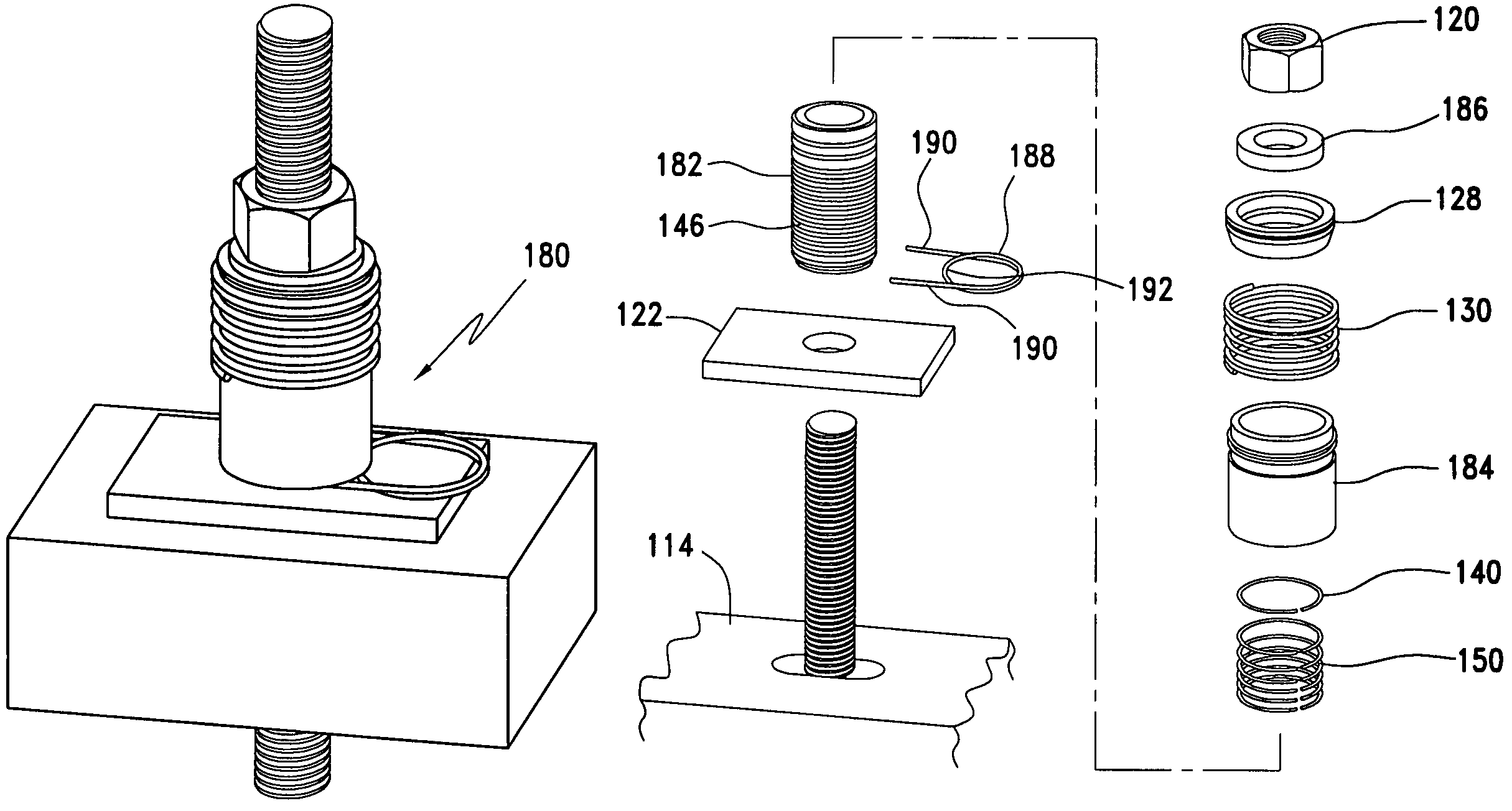
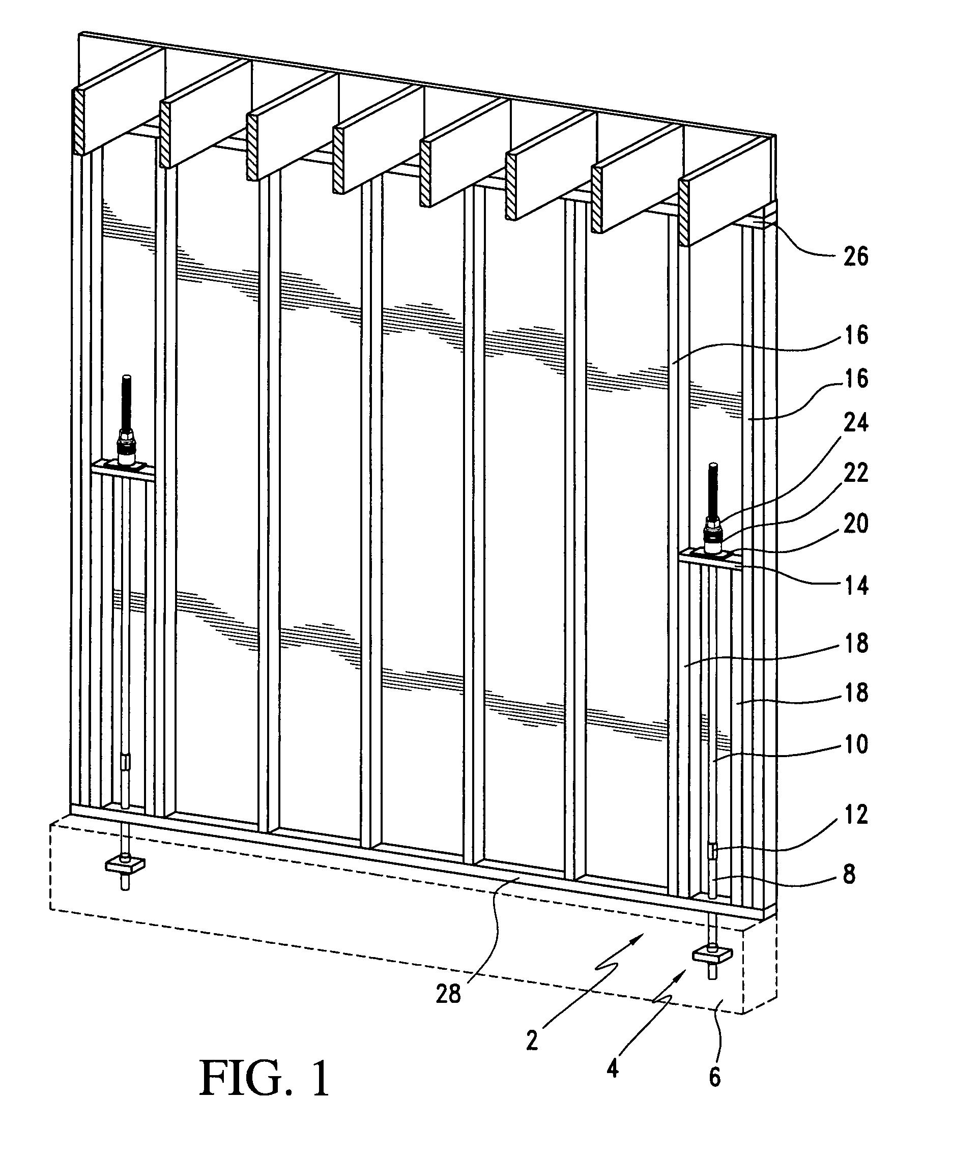
[0053]Referring to FIG. 1, a hold down system 2 made in accordance with the present invention is disclosed. The system 2 includes a foundation anchor 4 operably attached to a foundation 6 of a building. The foundation anchor 4 includes a threaded rod 8 attached to another threaded or tie-rod rod 10 by means of a coupling 12. A bridge member 14 spans between two adjacent studs 16 and is supported by a pair of reinforcement studs 18. A bearing plate 20 sits on top of the bridge member 14. The threaded rod 10 extends through the bridge member 14 and the bearing plate 20 through respective openings. A hold down device 22 is secured between the bearing plate 20 and a nut 24. The hold down device 22, which will be described below, is an expanding fastener assembly used to take up any slack that may develop in the tie-rod 10 due to shrinkage in the building wall.

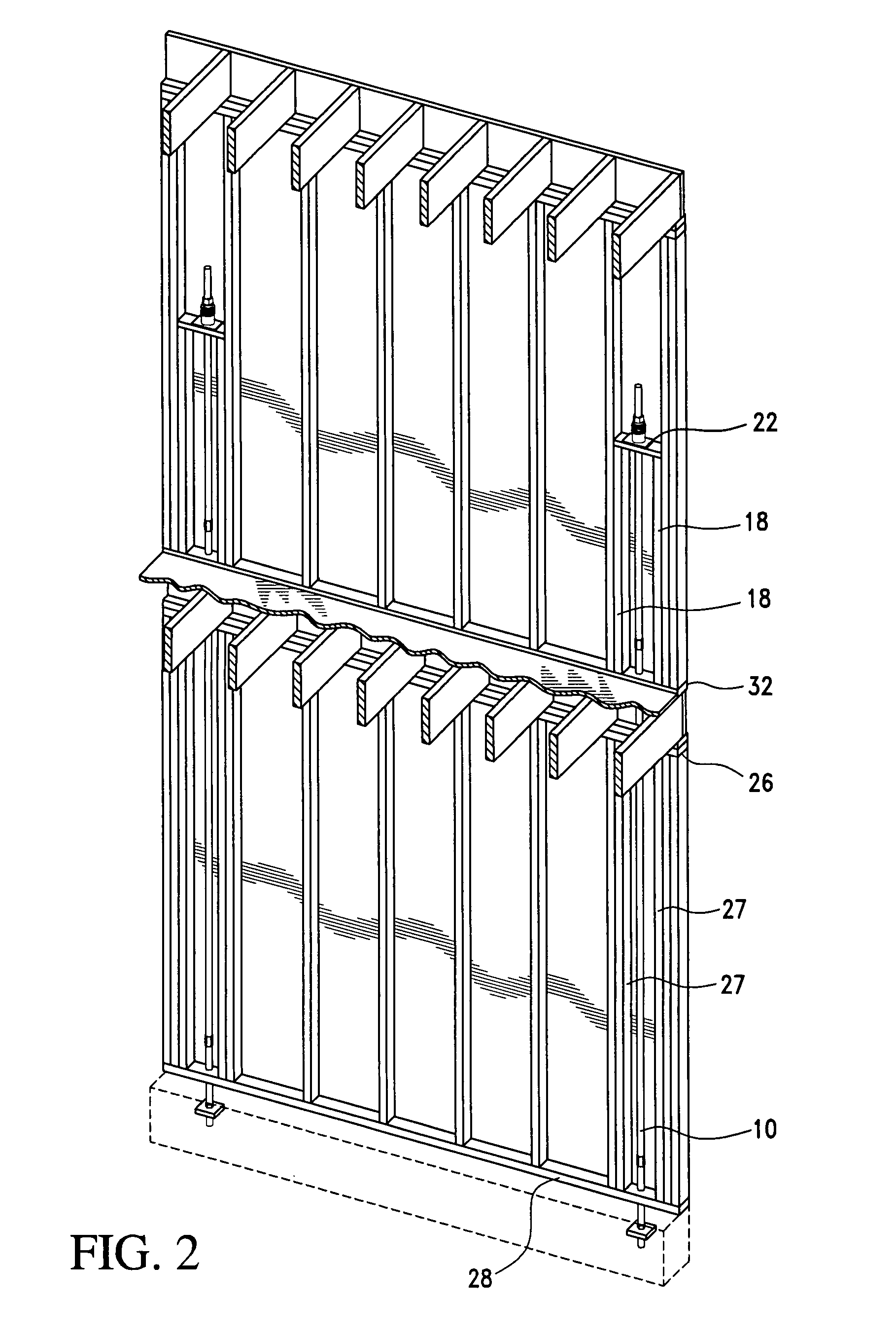
[0054]FIG. 1 discloses a hold down system as used in a one story structure. The reinforcement studs 18 terminate between the top ...


PUM


Abstract

A fastener assembly comprises a first cylindrical member disposed within a second cylindrical member. One of the first and second cylindrical members is movable relative to the other in a first direction. The other one of the first and second cylindrical members is locked relative to the one in a second direction opposite to the first direction. A spring is operably attached to the first and second cylindrical members to urge one of the first and second cylindrical members in the first direction. A removable member is operably associated with the first and second cylindrical members to prevent one of the first and second cylindrical members from moving in the first direction prior to removing the removable member. The removable member is configured to be pulled out to allow one of the first and second cylindrical members to move in the first direction.

Description

RELATED APPLICATION[0001]This is a nonprovisional application claiming the priority benefit of provisional application Ser. No. 60 / 843,698, filed Sep. 12, 2006, which is hereby incorporated by reference.FIELD OF THE INVENTION[0002]The present invention is generally directed to a tension hold down system used in walls in light frame construction to resist uplift and to compensate for wood shrinkage in wood frame construction and compression loading.BACKGROUND OF THE INVENTION[0003]Prior art hold down systems, such as one disclosed in U.S. Pat. No. 6,951,078, typically use a tie-rod that extends inside a stud wall from the foundation to the top floor. Field conditions and the quality of the installer are such that the tie-rod may not be installed perpendicular to the cross or bridge member to which the tie-rod is to be secured. In such a situation, the bearing surface of the bridge member and the hold down device may not align properly for good bearing contact due to the out-of vertic...

Claims


Application Information

Patent Timeline
Patent Type & Authority Patents(United States)
IPC IPC(8): E02D27/00
CPCE02D27/34E04B1/2604E04H9/14F16B43/00E04B2001/2688E04B2001/3583Y02A50/00E04B1/4157E04B2/70
Inventor ESPINOSA, THOMAS M.
Owner CETRES HLDG LLC
Why Eureka
Try Eureka