Rotary drag bit and methods therefor

a rotary drag bit and cutting element technology, applied in the field can solve the problems of shortened life of rotary drag bits using such cutting elements, shortened life wear of cutting elements of rotary drag bits, so as to prolong reduce stress on primary cutters, and improve the life of cutters

Active Publication Date: 2010-07-27
BAKER HUGHES INC
View PDF67 Cites 37 Cited by
  • Summary
  • Abstract
  • Description
  • Claims
  • Application Information

AI Technical Summary

Benefits of technology

[0011]Accordingly, embodiments of a rotary drag bit comprising a primary cutter row having at least one primary cutter, and at least two additional cutters configured relative to one another. In one embodiment, the cutters are backup cutters of a cutter group located in respective first and second trailing cutter rows, oriented relative to one another, and positioned to substantially follow the at least one primary cutter. The rotary drag bit life is extended by the backup cutter group, making the bit more durable and extending the life of the cutters. Further, the cutters may be selectively configured to engage and fracture a subterranean formation material being drilled, providing improved bit life and reduced stress upon the primary cutters.

Problems solved by technology

While the PDC cutting element improves drill bit efficiency in drilling many subterranean formations, the PDC cutting element is nonetheless prone to wear when exposed to certain drilling conditions, resulting in a shortened life of a rotary drag bit using such cutting elements.
The decrease in the penetration rate is a manifestation that the cutting elements of the rotary drag bit are wearing out, particularly when other drilling parameters remain constant.
While researchers continue to develop and seek out improvements for longer lasting cutters or generalized improvements to cutter performance, they fail to accommodate or implement an engineered approach to achieving longer drag bit life by maintaining or increasing ROP by taking advantage of cutting element wear rates.
Also, it is believed that conventional backup cutters in combination with their associated primary cutters may undesirably lead to bailing of the blade area with formation material.

Method used


Image

  • Rotary drag bit and methods therefor
  • Rotary drag bit and methods therefor
  • Rotary drag bit and methods therefor

Examples


first embodiment

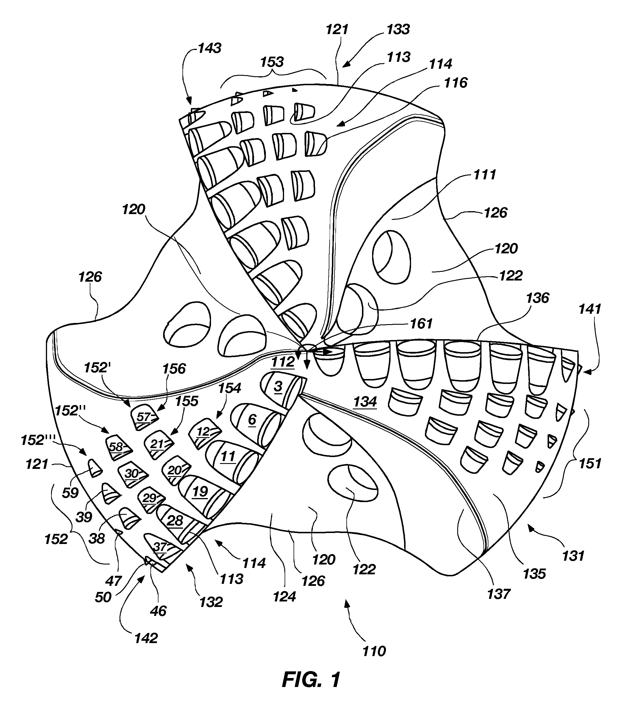
[0067]In accordance with the invention as shown in FIG. 1, the rotary drag bit 110 comprises three blades 131, 132, 133, three primary cutter rows 141, 142, 143 and three backup cutter groups 151, 152, 153, respectively. While three backup cutter groups 151, 152, 153 are included, it is contemplated that the rotary drag bit 110 may include one backup cutter group on one of the blades or a plurality of backup cutter groups on each blade greater or less than that illustrated. Further, it is contemplated that the rotary drag bit 110 may have more or fewer blades than the three illustrated. Each of the backup cutter groups 151, 152, 153 may have one or more backup cutter sets. For example, without limitation, the backup cutter group 152 includes three backup cutter sets 152′, 152″, 152′″. A detailed description of backup cutter sets 152′, 152″, 152′″ of the backup cutter group 152 is now provided.

[0068]Each primary cutter row 141, 142, 143 is arranged upon each blade 131, 132, 133, resp...

second embodiment

[0084]FIG. 5 shows a frontal view of a rotary drag bit 210 in accordance with the invention. The rotary drag bit 210 comprises six blades 231, 231′, 232, 232′, 233, 233′, each having a primary or first cutter row 241 and a second cutter row 251 extending from the center line C / L of the rotary drag bit 210. The cutter rows 241, 251 include cutters 214 coupled to cutter pockets 216 of the blades 231, 231′, 232, 232′, 233, 233′. It is contemplated that each blade 231, 231′, 232, 232′, 233, 233′ may have more or fewer cutter rows 241, 251 than the two that are illustrated. Also, each of the cutter rows 241, 251 may have fewer or greater numbers of cutters 214 than illustrated on each of the blades 231, 231′, 232, 232′, 233, 233′. In this embodiment, blades 231, 232, 233 are primary blades and blades 231′, 232′, 233′ are secondary blades. The secondary blades 231′, 232′, 233′ provide support for adding additional cutters 214, particularly, in the nose region 262 (see FIG. 6) where the wo...

fourth embodiment

[0116]The cutters 514 in cutter rows 541, 542, 543, 544, 545, 546 are fully exposed primary cutters as shown in FIG. 23, which shows a cutter and blade profile 530 for the invention. The rotary drag bit 510 has a cutter density of 51 cutters and a profile as represented by cutter and blade profile 530. The cutters 514 are numbered 1 through 51. The cutters 1-51, while they may include aspects of other embodiments of the invention, are not to be confused with the numbered cutters of the other embodiments of the invention. The cutters 514 in cutter rows 544, 545, 546 are positioned in adjacent rotary paths and fully exposed with respect to the cutters 514 in cutter rows 541, 542, 543 allowing the cutters 514 to provide the diamond volume in certain radial locations on the drag bit in order to optimize formation material removal while controlling cutter wear. In this respect, cutters 1-51 provide the cutter profile conventionally encountered on a six-bladed drag bit, however the cutter...


PUM


Abstract

A rotary drag bit includes a primary cutter row comprising at least one primary cutter, and at least two additional cutters configured relative to one another. In one embodiment, the cutters are backup cutters of a backup cutter group located in respective first and second trailing cutter rows, oriented relative to one another, and positioned to substantially follow the at least one primary cutter. The rotary drag bit life is extended by the backup cutter group, making the bit more durable and extending the life of the cutters. In other of the embodiments, the cutters are configured to selectively engage a subterranean formation material being drilled, providing improved bit life and reduced stress upon the cutters. Still other embodiments of rotary drag bits include backup cutter configurations having different backrake angles and siderake angles, including methods therefor.

Description

CROSS-REFERENCE TO RELATED APPLICATION[0001]This application claims the benefit of U.S. Provisional Patent Application Ser. No. 60 / 897,457, filed Jan. 25, 2007, pending, for “ROTARY DRAG BIT,” the entire disclosure of which is hereby incorporated herein by this reference.[0002]This application is also related to U.S. patent application Ser. No. 11 / 862,440, filed Sep. 27, 2007, pending, for ROTARY DRAG BITS HAVING A PILOT CUTTER CONFIGURATION AND METHOD TO PRE-FRACTURE SUBTERRANEAN FORMATIONS THEREWITH, which claims the benefit of U.S. Provisional Patent Application Ser. No. 60 / 873,349, filed Dec. 7, 2006, for “ROTARY DRAG BITS HAVING A PILOT CUTTER CONFIGURATION AND METHOD TO PRE-FRACTURE SUBTERRANEAN FORMATIONS THEREWITH. This application is also related to U.S. patent application Ser. No. 12 / 019,814, filed Jan. 25, 2008, pending, for ROTARY DRAG BIT, which claims the benefit of U.S. Provisional Patent Application Ser. No. 60 / 897,457 filed Jan. 25, 2007, for ROTARY DRAG BIT. This a...

Claims


Application Information

Patent Timeline
Patent Type & Authority Patents(United States)
IPC IPC(8): E21B10/46
CPCE21B10/43E21B10/55
Inventor MCCLAIN, ERIC E.GAVIA, DAVIDSNELL, LANE E.HOINES, JASON E.ISBELL, MATTHEW R.DOSTER, MICHAEL L.
Owner BAKER HUGHES INC
Why Eureka
Try Eureka