Solar powered aerial vehicle

a solar energy and aerial vehicle technology, applied in the field of aircraft and aerial vehicles, can solve the problems of reducing the return rate of solar energy, affecting the design of solar energy-based aerial vehicles, and only limited operational value of aerial vehicles capable of operating only near the equator or in the long daylight hours of the summer months. achieve the effect of solar energy

Active Publication Date: 2010-07-27
THE BOEING CO
View PDF13 Cites 45 Cited by
  • Summary
  • Abstract
  • Description
  • Claims
  • Application Information

AI Technical Summary

Benefits of technology

[0011]In accordance with the exemplary embodiments disclosed herein, solar powered aerial vehicles are provide that incorporate a novel “tracking solar sail” that enables significantly more solar energy to be collected than that of more convention wind-body-tail or all-wing aerial vehicles, thereby yielding capabilities of virtually indefinite (“24 / 7”) flight durations at northern latitudes during the winter months and significantly exceeding those of previous solar powered aerial vehicles.
[0012]In one embodiment, the novel tracking solar sail comprises a non-lift-providing panel located behind the wing and having solar cells located on only one side, which tracks the sun's elevation as the aerial vehicle maneuvers and / or the sun moves across the sky, thereby approximately doubling the amount of solar energy that can be collected in winter months at high latitudes and yielding additional altitude, latitude and / or payload capabilities, as compared to aerial vehicle designs that lack the solar sail.

Problems solved by technology

Aerial vehicles that are capable of operating only near the equator or in the long daylight hours of the summer months have only limited operational value.
Prior solar powered aerial vehicle designs are significantly limited by the vehicle's limited surface areas and surface norms, i.e., the wings typically comprise the largest vehicle surface available for the collection of solar energy, and are typically disposed horizontally relative to the Earth.
This arrangement can be disadvantageous, especially in the winter at high latitudes where the angle of the sun is low.
Moreover, the tactic of simply adding more wing, fuselage or tail surface area beyond the minimum needed for the vehicle to fly so as to collect additional solar energy therewith rapidly encounters a point of diminishing returns.
This is because the additional surface area results in additional vehicle weight and drag that require more energy to fly than the additional solar energy collected by the added surface area.
Higher efficiency and lighter solar cells and energy storage devices could theoretically solve the problem, but the technologies necessary do not exist currently, and are not projected to exist for the next several decades.
HELIOS flew only during the daytime (with limited operation at night using batteries), and never flew a full day-night cycle.
Analyses show that aerial vehicles incorporating the HELIOS technology would not be capable of operation at northern latitudes in the winter without solar cell and power storage efficiencies that are not expected to exist for some decades in the future.
This concept significantly reduced the technology needs of solar cells and power storage, but added the technology and operational constraints of formation flight that some potential users found undesirable.
The SPFF vehicles were actually built and flown, but these did not incorporate solar powered propulsion systems.
However, this vehicle lacks the capability of solar powered flight in northern latitudes during the winter months.
Other solar powered aerial vehicles have been developed over the past 20 or more years, but none has a documented capability of long-term operation in the critical conditions of northern latitudes and during the winter.
However, without significant increases in solar cell and power storage technologies over what is planned for development in the next several decades, these vehicles all lack the capability of year-round flight at northern latitudes during the winter months, mainly due to a shortage of solar energy collection capability.
A long-felt but as yet unsatisfied need therefore exists for aerial vehicles having vertical surfaces or elevation-tracking surfaces that can be oriented almost vertically in winter conditions and at high latitudes and thereby enable the collection of significantly more solar energy at this critical time of year and latitude condition.

Method used


Image

  • Solar powered aerial vehicle
  • Solar powered aerial vehicle
  • Solar powered aerial vehicle

Examples


Embodiment Construction

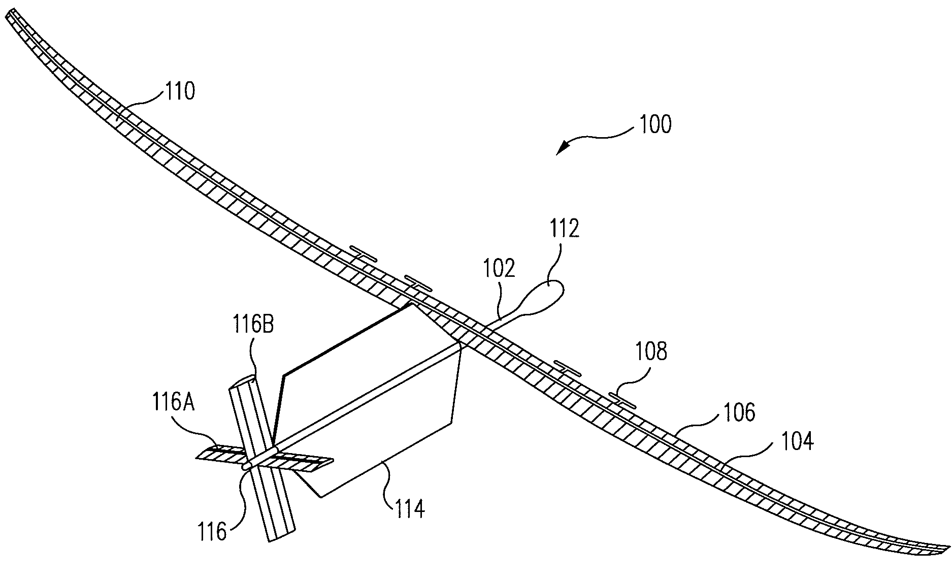
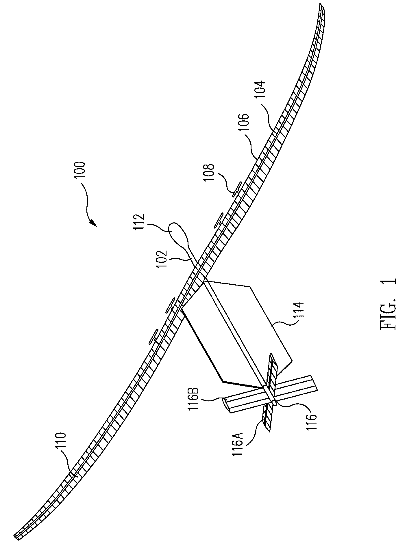
[0022]FIG. 1 is a perspective view of an exemplary embodiment of an unmanned solar powered aerial vehicle (USPAV) 100. The vehicle comprises an elongated tubular fuselage 102 and an elongated, relatively narrow (i.e., high-aspect-ratio) wing 104 adapted for efficient, high-altitude, relatively slow flight. The wing mounts a plurality of electric motors 106, each equipped with, e.g., a variable- or fixed-pitch propeller 108, and in one embodiment, may also include an array of solar cells 110 disposed on the upper surface thereof. An enlarged payload and control housing 112 is located at the nose end of the fuselage, and is adapted to carry flight command and control avionics and instrumentation, rechargeable batteries or other energy storage elements, and a payload, such as surveillance cameras, radio or television signal broadcasting or repeating equipment, weather sensors and data recorders, or the like.

[0023]Of importance, the exemplary vehicle 100 further includes a tracking sola...


PUM


Abstract

A solar powered aerial vehicle includes an elongated airframe incorporating lifting and control surfaces, a mechanism for propelling the airframe through the air such that lift developed by the lifting surface is equal to or greater than the weight of the aerial vehicle, a planar solar sail coupled to the airframe and having at least one surface adapted to collect solar energy during the day and to power the propelling mechanism with a first portion of the energy collected, and an apparatus such as a fuel cell / electrolyzer for storing a second portion of the solar energy collected by the solar sail during the day and for powering the propelling mechanism with the second portion of energy during the night. The vehicle is capable of continuous operation at northern latitudes and during the winter months for extended periods without landing or refueling.

Description

BACKGROUND[0001]This disclosure relates to aircraft and aerial vehicles, in general, and in particular, to a solar powered aerial vehicle that is capable of continuous flight at high latitudes during the winter for extended periods without landing or refueling.[0002]During the past 30-40 years, several efforts have been made to develop solar powered aerial vehicles, primarily unmanned, that are capable of achieving flight durations of from several months to years without needing to land or refuel. These vehicles typically employ solar cells located on their exterior surfaces, primarily their wing surfaces, to capture solar energy during the day. They then use some of that energy to fly during the day, and store excess energy in an energy storage device, e.g., a battery, flywheel, fuel cell, or other storage device, to power the vehicle during the dark of night, when the sun is not available for collection of power.[0003]Aerial vehicles that are capable of operating only near the equ...

Claims


Application Information

Patent Timeline
Patent Type & Authority Patents(United States)
IPC IPC(8): B64C1/00
CPCB64C39/024B64D27/24B64C2201/021B64C2201/042B64C2201/127Y02T50/62Y02T50/60B64U10/25B64U50/19B64U50/31B64U50/32B64U2101/31B64U2101/30
Inventor MILLER, GERALD D
Owner THE BOEING CO
Why Eureka
Try Eureka